497 - 2067 specifications
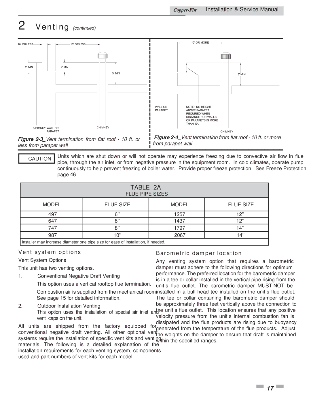
Lochinvar 497 - 2067 is a highly efficient and versatile condensing boiler that is designed to meet the diverse heating needs of residential and commercial applications. Known for its impressive performance and advanced technology, the Lochinvar 497 - 2067 has garnered a reputation as a reliable choice among heating professionals.One of the standout features of the Lochinvar 497 - 2067 is its impressive thermal efficiency. The boiler boasts an efficiency rating of up to 95% AFUE (Annual Fuel Utilization Efficiency), allowing users to significantly reduce their energy costs while minimizing environmental impact. This efficiency is facilitated by its innovative condensing technology, which captures and reuses heat from exhaust gases for optimal performance.
The Lochinvar 497 - 2067 is equipped with a robust stainless steel heat exchanger designed to handle high temperatures and ensure long-lasting performance. The heat exchanger’s design maximizes heat transfer, while its corrosion-resistant properties guarantee durability over time. This contributes to the boiler's overall longevity and serviceability, reducing the need for frequent replacements.
Control is another critical feature of the Lochinvar 497 - 2067. The boiler comes with an advanced control system that enables easy management of system operations. Users can take advantage of features such as outdoor reset control, which adjusts the temperature of the boiler based on external weather conditions, enhancing system efficiency and comfort.
In terms of safety, the Lochinvar 497 - 2067 incorporates several cutting-edge safety features, including a flame detection system and multiple safety shut-off devices. These safeguards help to ensure the safe operation of the boiler, providing peace of mind to users and heating professionals alike.
Another important characteristic is the compact design of the Lochinvar 497 - 2067, which allows for flexible installation in various settings, including tight spaces. Its lightweight structure further simplifies the installation process, making it a practical choice for contractors.
In summary, the Lochinvar 497 - 2067 is an exceptional high-efficiency condensing boiler that combines advanced technology, durability, and ease of use. With its impressive thermal efficiency, superior heat exchanger design, advanced control systems, and enhanced safety measures, it stands out as a top choice for those seeking reliable heating solutions. This boiler not only meets but exceeds modern demands for energy efficiency and performance, solidifying its position in the market.

