3 Gas connections (continued)

Gas connection

All gas connections must be made with pipe joint compound resistant to the action of liquefied petroleum (L.P.) and natural gases. All piping must comply with local codes and ordinances. Piping installations must comply with approved standards and practices.

1.Make sure gas line is a separate line direct from the meter unless the existing gas line is of sufficient capacity. Verify pipe size with your gas supplier.

2.Use new, properly threaded black iron pipe free from chips. If you use tubing, make sure the ends are cut square, deburred and clean. Make all tubing bends smooth and without deformation. Avoid flexible gas connections. Internal diameter of flexible lines may not provide unit with proper volume of gas.

3.Install a manual main gas shutoff valve at the unit’s gas inlet, outside of the unit.

4.Run pipe or tubing to the unit’s gas inlet. If you use tubing, obtain a tube to pipe coupling to connect the tubing to the unit’s gas inlet.

5.Install a sediment trap in the supply line to the unit’s gas inlet (see FIG. 3-1).

6.Apply a moderate amount of good quality pipe compound (do not use Teflon tape) to pipe only, leaving two end threads bare.

7.Remove seal over gas inlet to unit.

8.Connect gas pipe to inlet of unit. Use wrench to support gas manifold on the unit.

9.For L.P. gas, consult your L.P. gas supplier for expert installation.

10.Ensure that all air is completely bled from the gas line before starting the ignition sequence. Start up without properly bleeding air from the gas line may require multiple reset functions of the ignition control module to achieve proper ignition.

Do not have any open flame in proximity to WARNING the gas line when bleeding air from the gas

line. Gas may be present.

Gas train and controls

NOTICE

The gas train and controls assembly

provided on this unit have been tested under


the applicable American National Standard


to meet minimum safety and performance


criteria such as safe lighting, combustion


and safety shutdown operation.

Installation & Service Manual

TABLE 3B

SUGGESTED GAS PIPE SIZE FOR

SINGLE UNIT INSTALLATIONS

Distance from Meter (in feet)

MODEL


0 - 50

51 - 100

101 - 200

201-300 301-500

497

1 1/4''

1 1/4''

1 1/2''

2''

2''

647

1 1/4''

1 1/2''

2''

2''

2 1/2''

747

1 1/2''

2''

2''

2 1/2''

2 1/2''

987

2''

2''

2 1/2''

2 1/2''

3''

1257

2''

2 1/2''

2 1/2''

3''

3''

1437

2 1/2''

2 1/2''

3''

3''

3 1/2''

1797

2 1/2''

3''

3''

3 1/2''

3 1/2''

2067

2 1/2''

3''

3''

3 1/2''

4''

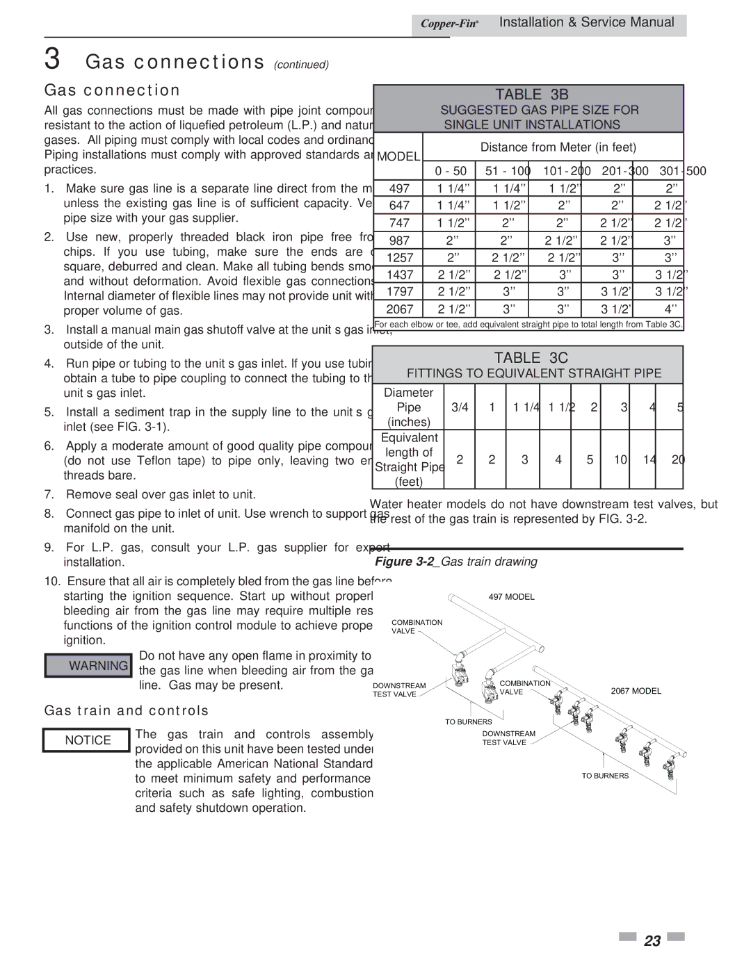
For each elbow or tee, add equivalent straight pipe to total length from Table 3C.

TABLE 3C

FITTINGS TO EQUIVALENT STRAIGHT PIPE

Diameter


Pipe

3/4

1

1 1/4

1 1/2

2

3

4

5

(inches)


Equivalent


length of

2

2

3

4

5

10

14

20

Straight Pipe


(feet)


Water heater models do not have downstream test valves, but the rest of the gas train is represented by FIG. 3-2.

Figure 3-2_Gas train drawing

497 MODEL

COMBINATION

VALVE

DOWNSTREAM

COMBINATION

2067 MODEL

VALVE

TEST VALVE


TO BURNERS

DOWNSTREAM

TEST VALVE

TO BURNERS

23

Page 23
Image 23
Lochinvar 497 - 2067 Gas connection, Gas train and controls, Suggested GAS Pipe Size for Single Unit Installations

497 - 2067 specifications

Lochinvar 497 - 2067 is a highly efficient and versatile condensing boiler that is designed to meet the diverse heating needs of residential and commercial applications. Known for its impressive performance and advanced technology, the Lochinvar 497 - 2067 has garnered a reputation as a reliable choice among heating professionals.

One of the standout features of the Lochinvar 497 - 2067 is its impressive thermal efficiency. The boiler boasts an efficiency rating of up to 95% AFUE (Annual Fuel Utilization Efficiency), allowing users to significantly reduce their energy costs while minimizing environmental impact. This efficiency is facilitated by its innovative condensing technology, which captures and reuses heat from exhaust gases for optimal performance.

The Lochinvar 497 - 2067 is equipped with a robust stainless steel heat exchanger designed to handle high temperatures and ensure long-lasting performance. The heat exchanger’s design maximizes heat transfer, while its corrosion-resistant properties guarantee durability over time. This contributes to the boiler's overall longevity and serviceability, reducing the need for frequent replacements.

Control is another critical feature of the Lochinvar 497 - 2067. The boiler comes with an advanced control system that enables easy management of system operations. Users can take advantage of features such as outdoor reset control, which adjusts the temperature of the boiler based on external weather conditions, enhancing system efficiency and comfort.

In terms of safety, the Lochinvar 497 - 2067 incorporates several cutting-edge safety features, including a flame detection system and multiple safety shut-off devices. These safeguards help to ensure the safe operation of the boiler, providing peace of mind to users and heating professionals alike.

Another important characteristic is the compact design of the Lochinvar 497 - 2067, which allows for flexible installation in various settings, including tight spaces. Its lightweight structure further simplifies the installation process, making it a practical choice for contractors.

In summary, the Lochinvar 497 - 2067 is an exceptional high-efficiency condensing boiler that combines advanced technology, durability, and ease of use. With its impressive thermal efficiency, superior heat exchanger design, advanced control systems, and enhanced safety measures, it stands out as a top choice for those seeking reliable heating solutions. This boiler not only meets but exceeds modern demands for energy efficiency and performance, solidifying its position in the market.