3 Gas connections (continued)

Combination gas valve/regulators equipped with integral vent limiters are not required to have vent or relief lines piped to the outdoors. The termination of the vent limited opening on the combination gas valve/regulator complies with the safety code requirements of CSD-1, CF-190(a) as shipped from the appliance manufacturer without the installation of additional vent lines.

Checking gas supply pressure

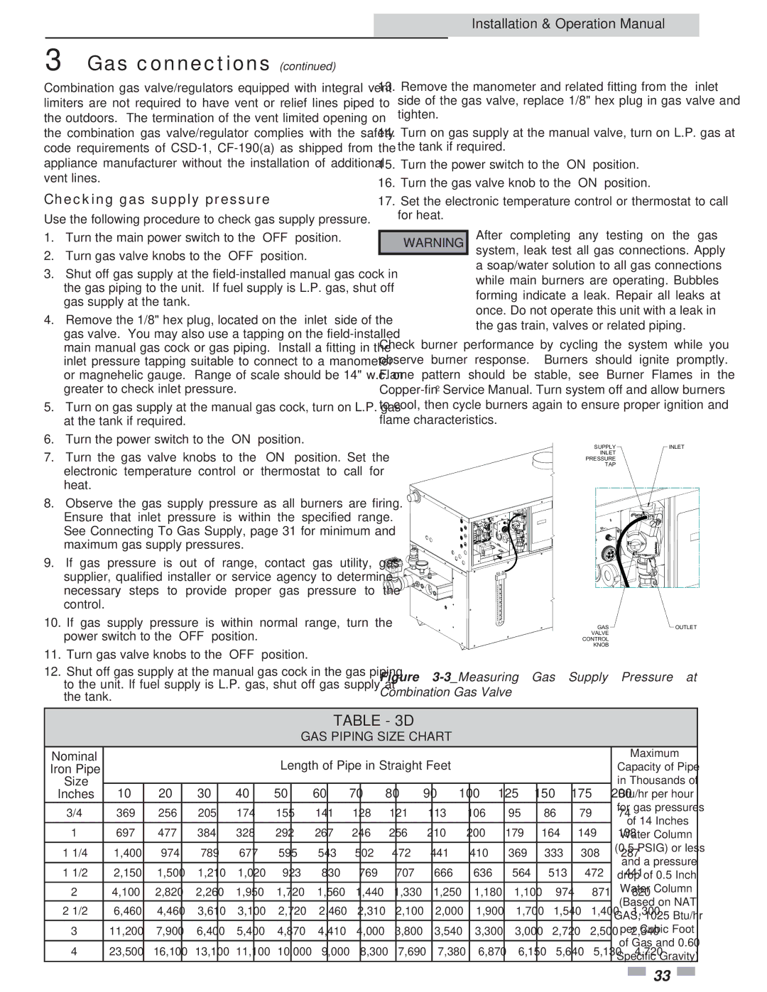
Use the following procedure to check gas supply pressure.

Installation & Operation Manual

13.Remove the manometer and related fitting from the “inlet” side of the gas valve, replace 1/8" hex plug in gas valve and tighten.

14.Turn on gas supply at the manual valve, turn on L.P. gas at the tank if required.

15.Turn the power switch to the “ON” position.

16.Turn the gas valve knob to the “ON” position.

17.Set the electronic temperature control or thermostat to call for heat.

1.

Turn the main power switch to the “OFF” position.

2.

Turn gas valve knobs to the “OFF” position.

3.

Shut off gas supply at the field-installed manual gas cock in


the gas piping to the unit. If fuel supply is L.P. gas, shut off


gas supply at the tank.

4.

Remove the 1/8" hex plug, located on the “inlet” side of the


gas valve. You may also use a tapping on the field-installed

￿WARNING

After completing any testing on the gas system, leak test all gas connections. Apply a soap/water solution to all gas connections while main burners are operating. Bubbles forming indicate a leak. Repair all leaks at once. Do not operate this unit with a leak in the gas train, valves or related piping.


main manual gas cock or gas piping. Install a fitting in the


inlet pressure tapping suitable to connect to a manometer


or magnehelic gauge. Range of scale should be 14" w.c. or


greater to check inlet pressure.

5.

Turn on gas supply at the manual gas cock, turn on L.P. gas


at the tank if required.

6.

Turn the power switch to the “ON” position.

7.

Turn the gas valve knobs to the “ON” position. Set the


electronic temperature control or thermostat to call for


heat.

8.

Observe the gas supply pressure as all burners are firing.


Ensure that inlet pressure is within the specified range.


See Connecting To Gas Supply, page 31 for minimum and


maximum gas supply pressures.

9.

If gas pressure is out of range, contact gas utility, gas


supplier, qualified installer or service agency to determine


necessary steps to provide proper gas pressure to the


control.

10.

If gas supply pressure is within normal range, turn the


power switch to the “OFF” position.

11.

Turn gas valve knobs to the “OFF” position.

12.

Shut off gas supply at the manual gas cock in the gas piping


to the unit. If fuel supply is L.P. gas, shut off gas supply at


the tank.

Check burner performance by cycling the system while you observe burner response. Burners should ignite promptly. Flame pattern should be stable, see Burner Flames in the Copper-fin2Service Manual. Turn system off and allow burners to cool, then cycle burners again to ensure proper ignition and flame characteristics.

SUPPLYINLET

INLET

PRESSURE

TAP

GASOUTLET

VALVE

CONTROL

KNOB

Figure 3-3_Measuring Gas Supply Pressure at Combination Gas Valve

TABLE - 3D

GAS PIPING SIZE CHART

Nominal


Length of Pipe in Straight Feet


Maximum

Iron Pipe


Capacity of Pipe

Size


in Thousands of

10

20

30

40

50

60

70

80

90

100

125

150

175

200

Inches

Btu/hr per hour

3/4

369

256

205

174

155

141

128

121

113

106

95

86

79

74

for gas pressures

of 14 Inches


1

697

477

384

328

292

267

246

256

210

200

179

164

149

138

Water Column

1 1/4

1,400

974

789

677

595

543

502

472

441

410

369

333

308

287

(0.5 PSIG) or less

and a pressure


1 1/2

2,150

1,500

1,210

1,020

923

830

769

707

666

636

564

513

472

441

drop of 0.5 Inch

24,100 2,820 2,260 1,950 1,720 1,560 1,440 1,330 1,250 1,180 1,100 974 871 820 Water Column (Based on NAT

2 1/2

6,460

4,460

3,610

3,100

2,720

2,460

2,310

2,100

2,000

1,900

1,700

1,540

1,400

1,300

GAS, 1025 Btu/hr

3

11,200

7,900

6,400

5,400

4,870

4,410

4,000

3,800

3,540

3,300

3,000

2,720

2,500

2,340

per Cubic Foot


of Gas and 0.60


423,500 16,100 13,100 11,100 10,000 9,000 8,300 7,690 7,380 6,870 6,150 5,640 5,130 4,720 Specific Gravity)

33

Page 33
Image 33
Lochinvar 2072, 502 operation manual Checking gas supply pressure, GAS Piping Size Chart

2072, 502 specifications

Lochinvar 2072,502 is an innovative and robust water-heating solution tailored for residential and commercial applications. This model represents a significant advancement in energy efficiency and performance, catering to the dynamic heating requirements of modern buildings.

One of the standout features of Lochinvar 2072,502 is its advanced thermal efficiency. With an impressive AFUE (Annual Fuel Utilization Efficiency) rating, the unit delivers exceptional heat output while minimizing energy consumption. This not only reduces utility bills for homeowners and businesses but also supports sustainability efforts by decreasing carbon footprints.

The Lochinvar 2072,502 incorporates cutting-edge technologies that set it apart in the market. It is equipped with advanced control systems that allow users to precisely manage heating outputs, ensuring optimal comfort while conserving energy. The user-friendly digital display provides real-time data, allowing for efficient monitoring and control.

Another significant characteristic of the Lochinvar 2072,502 is its robust stainless-steel construction. This feature enhances the unit's durability and longevity, ensuring reliable performance even in challenging conditions. The high-quality materials also contribute to maintaining consistent water temperatures, which is essential for both residential and commercial heating needs.

The Lochinvar 2072,502 operates silently, making it ideal for installations in areas where noise is a concern. Its compact design allows for flexible installation options, fitting seamlessly into various spaces, whether it’s a utility room, basement, or outdoor area.

Furthermore, the unit supports multiple venting options, accommodating different building architectures and layouts. This versatility makes it an ideal choice for new builds and retrofitting existing systems.

Maintenance is streamlined with the Lochinvar 2072,502, as it features a self-diagnostics system that simplifies troubleshooting. Regular service check-ups are made easier with accessible components, allowing technicians to perform maintenance tasks efficiently.

In summary, the Lochinvar 2072,502 stands out for its high efficiency, advanced technology, durability, and flexible installation options. It is an ideal choice for those seeking a reliable and technologically advanced water-heating solution that meets the challenges of contemporary heating demands while promoting energy savings and environmental responsibility.