5 Electrical connections

Alarm contacts

The SMART SYSTEM control closes another set of contacts whenever the heater is locked out or the power is turned off. This can be used to turn on an alarm, or signal a Building Management System that the pool heater is down.

Wiring of the cascade

When wiring the heaters for Cascade operation, select one heater as the Leader. The remaining heaters will be designated as Members. See page 48, Configuration of the Cascade for a detailed explanation of this procedure.

The return sensor of the Leader heater should be placed in the main system piping loop, upstream of the water being supplied to all the heaters (see FIG.’s 4-5, 4-6, and 4-7). The return sensors on the remaining Member heaters may also be placed in the same location as the Leader or they can be placed in each Member’s PVC piping loop in the Alternate sensor location, using the tapped sensor hole (FIG. 4-3). Should the Leader heater ever need to be replaced with one of the Member heaters in the Cascade, that Member’s sensor should be relocated to the previous lead heater’s supply sensor location for optimum operation of the cascaded units.

The supply/limit sensors of all cascaded heaters MUST be placed downstream, in the main system piping loop in the blended water, going out to the pool (FIG.’s 4-5, 4-6, and 4-7). The supply/limit sensor also serves as a high temperature limit for pool supply water and failure to locate all sensors in the blended water going out to the pool could result in higher temperature water than desired being discharged to the pool.

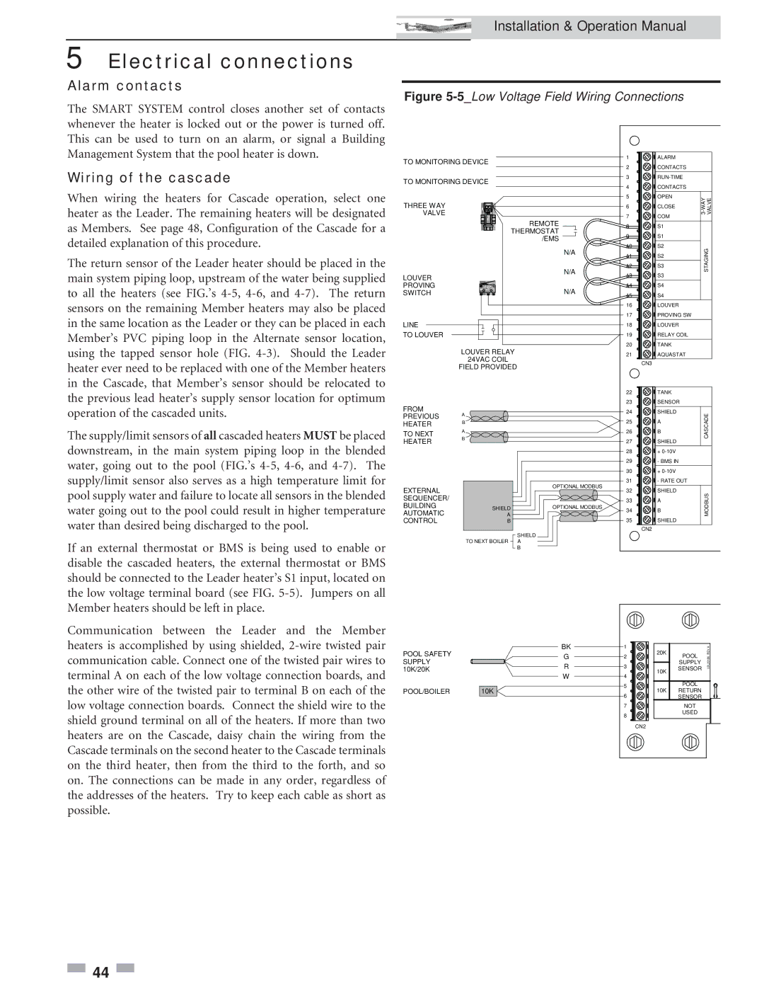
If an external thermostat or BMS is being used to enable or disable the cascaded heaters, the external thermostat or BMS should be connected to the Leader heater’s S1 input, located on the low voltage terminal board (see FIG. 5-5). Jumpers on all Member heaters should be left in place.

Communication between the Leader and the Member heaters is accomplished by using shielded, 2-wire twisted pair communication cable. Connect one of the twisted pair wires to terminal A on each of the low voltage connection boards, and the other wire of the twisted pair to terminal B on each of the low voltage connection boards. Connect the shield wire to the shield ground terminal on all of the heaters. If more than two heaters are on the Cascade, daisy chain the wiring from the Cascade terminals on the second heater to the Cascade terminals on the third heater, then from the third to the forth, and so on. The connections can be made in any order, regardless of the addresses of the heaters. Try to keep each cable as short as possible.

Installation & Operation Manual

Figure 5-5_Low Voltage Field Wiring Connections

TO MONITORING DEVICE


1

ALARM


2

CONTACTS


TO MONITORING DEVICE


3

RUN-TIME


4

CONTACTS


5

OPEN

WAY-3

VALVE

THREE WAY


6

CLOSE

VALVE


7

COM


REMOTE


8

S1


THERMOSTAT

9

S1


/EMS


10

S2


N/A

STAGING


11

S2


N/A

12

S3


LOUVER


13

S3


PROVING


N/A

14

S4


SWITCH


15

S4


16

LOUVER


17

PROVING SW


LINE


18

LOUVER


TO LOUVER


19

RELAY COIL


LOUVER RELAY


20

TANK


21

AQUASTAT


24VAC COIL


CN3


FIELD PROVIDED


22

TANK


FROM


23

SENSOR


A


24

SHIELD

CASCADE

TO NEXT


PREVIOUS


25

A


HEATER

B


A


26

B


HEATER

B


27

SHIELD


28

+ 0-10V


29

- BMS IN


30

+ 0-10V


OPTIONAL MODBUS

31

- RATE OUT


EXTERNAL


32

SHIELD


A


MODBUS

AUTOMATIC


SEQUENCER/


33

A


BUILDING

SHIELD

OPTIONAL MODBUS

34

B


CONTROL

B


35

SHIELD


SHIELD


CN2


TO NEXT BOILER

A


B


BK

1


A

POOL SAFETY


G

2

20K

POOL

REV


LBL20186

SUPPLY


R

3


SENSOR


SUPPLY


10K/20K


W

4

10K


POOL


10K


5


POOL/BOILER


10K

RETURN


6


SENSOR


7


NOT


8


USED


CN2


44

Page 44
Image 44
Lochinvar 502, 2072 operation manual Alarm contacts, Wiring of the cascade

2072, 502 specifications

Lochinvar 2072,502 is an innovative and robust water-heating solution tailored for residential and commercial applications. This model represents a significant advancement in energy efficiency and performance, catering to the dynamic heating requirements of modern buildings.

One of the standout features of Lochinvar 2072,502 is its advanced thermal efficiency. With an impressive AFUE (Annual Fuel Utilization Efficiency) rating, the unit delivers exceptional heat output while minimizing energy consumption. This not only reduces utility bills for homeowners and businesses but also supports sustainability efforts by decreasing carbon footprints.

The Lochinvar 2072,502 incorporates cutting-edge technologies that set it apart in the market. It is equipped with advanced control systems that allow users to precisely manage heating outputs, ensuring optimal comfort while conserving energy. The user-friendly digital display provides real-time data, allowing for efficient monitoring and control.

Another significant characteristic of the Lochinvar 2072,502 is its robust stainless-steel construction. This feature enhances the unit's durability and longevity, ensuring reliable performance even in challenging conditions. The high-quality materials also contribute to maintaining consistent water temperatures, which is essential for both residential and commercial heating needs.

The Lochinvar 2072,502 operates silently, making it ideal for installations in areas where noise is a concern. Its compact design allows for flexible installation options, fitting seamlessly into various spaces, whether it’s a utility room, basement, or outdoor area.

Furthermore, the unit supports multiple venting options, accommodating different building architectures and layouts. This versatility makes it an ideal choice for new builds and retrofitting existing systems.

Maintenance is streamlined with the Lochinvar 2072,502, as it features a self-diagnostics system that simplifies troubleshooting. Regular service check-ups are made easier with accessible components, allowing technicians to perform maintenance tasks efficiently.

In summary, the Lochinvar 2072,502 stands out for its high efficiency, advanced technology, durability, and flexible installation options. It is an ideal choice for those seeking a reliable and technologically advanced water-heating solution that meets the challenges of contemporary heating demands while promoting energy savings and environmental responsibility.