4 Water connections (continued)

Pumped Automatic Bypass

This is a high efficiency pool heater which requires a special pumped bypass for proper operation. The bypass assembly supplied with the pool heater includes a pump and a 3-way mixing valve. All piping to connect the filter system to the pool heater is made directly to the bypass piping on the pool heater.

Installation & Operation Manual

Note: The actuator handle is not used when the outdoor cover is installed. The handle is attached to the underside of the actuator for storage.

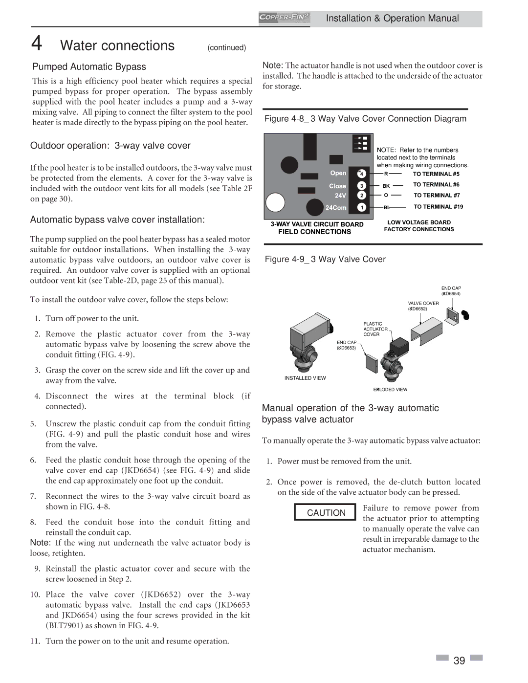
Figure 4-8_3 Way Valve Cover Connection Diagram

Outdoor operation: 3-way valve cover

If the pool heater is to be installed outdoors, the 3-way valve must be protected from the elements. A cover for the 3-way valve is included with the outdoor vent kits for all models (see Table 2F on page 30).

Automatic bypass valve cover installation:

*

FIELD CONNECTIONS

*NOTE: Refer to the numbers located next to the terminals when making wiring connections.

RTO TERMINAL #5

BK


TO TERMINAL #6


OTO TERMINAL #7

BL TO TERMINAL #19

LOW VOLTAGE BOARD FACTORY CONNECTIONS

The pump supplied on the pool heater bypass has a sealed motor suitable for outdoor installations. When installing the 3-way automatic bypass valve outdoors, an outdoor valve cover is required. An outdoor valve cover is supplied with an optional outdoor vent kit (see Table-2D, page 25 of this manual).

To install the outdoor valve cover, follow the steps below:

1.Turn off power to the unit.

2.Remove the plastic actuator cover from the 3-way automatic bypass valve by loosening the screw above the conduit fitting (FIG. 4-9).

3.Grasp the cover on the screw side and lift the cover up and away from the valve.

4.Disconnect the wires at the terminal block (if connected).

5.Unscrew the plastic conduit cap from the conduit fitting (FIG. 4-9) and pull the plastic conduit hose and wires from the valve.

6.Feed the plastic conduit hose through the opening of the valve cover end cap (JKD6654) (see FIG. 4-9) and slide the end cap approximately one foot up the conduit.

7.Reconnect the wires to the 3-way valve circuit board as shown in FIG. 4-8.

8.Feed the conduit hose into the conduit fitting and reinstall the conduit cap.

Note: If the wing nut underneath the valve actuator body is loose, retighten.

9.Reinstall the plastic actuator cover and secure with the screw loosened in Step 2.

10.Place the valve cover (JKD6652) over the 3-way automatic bypass valve. Install the end caps (JKD6653 and JKD6654) using the four screws provided in the kit (BLT7901) as shown in FIG. 4-9.

11.Turn the power on to the unit and resume operation.

Figure 4-9_3 Way Valve Cover

END CAP (JKD6654)

VALVE COVER (JKD6652)

PLASTIC

ACTUATOR

COVER

END CAP (JKD6653)

INSTALLED VIEW

EXPLODED VIEW

Manual operation of the 3-way automatic bypass valve actuator

To manually operate the 3-way automatic bypass valve actuator:

1.Power must be removed from the unit.

2.Once power is removed, the de-clutch button located on the side of the valve actuator body can be pressed.

CAUTION Failure to remove power from the actuator prior to attempting

to manually operate the valve can result in irreparable damage to the actuator mechanism.

39

Page 39
Image 39
Lochinvar 2072 Pumped Automatic Bypass, Outdoor operation 3-way valve cover, Automatic bypass valve cover installation

2072, 502 specifications

Lochinvar 2072,502 is an innovative and robust water-heating solution tailored for residential and commercial applications. This model represents a significant advancement in energy efficiency and performance, catering to the dynamic heating requirements of modern buildings.

One of the standout features of Lochinvar 2072,502 is its advanced thermal efficiency. With an impressive AFUE (Annual Fuel Utilization Efficiency) rating, the unit delivers exceptional heat output while minimizing energy consumption. This not only reduces utility bills for homeowners and businesses but also supports sustainability efforts by decreasing carbon footprints.

The Lochinvar 2072,502 incorporates cutting-edge technologies that set it apart in the market. It is equipped with advanced control systems that allow users to precisely manage heating outputs, ensuring optimal comfort while conserving energy. The user-friendly digital display provides real-time data, allowing for efficient monitoring and control.

Another significant characteristic of the Lochinvar 2072,502 is its robust stainless-steel construction. This feature enhances the unit's durability and longevity, ensuring reliable performance even in challenging conditions. The high-quality materials also contribute to maintaining consistent water temperatures, which is essential for both residential and commercial heating needs.

The Lochinvar 2072,502 operates silently, making it ideal for installations in areas where noise is a concern. Its compact design allows for flexible installation options, fitting seamlessly into various spaces, whether it’s a utility room, basement, or outdoor area.

Furthermore, the unit supports multiple venting options, accommodating different building architectures and layouts. This versatility makes it an ideal choice for new builds and retrofitting existing systems.

Maintenance is streamlined with the Lochinvar 2072,502, as it features a self-diagnostics system that simplifies troubleshooting. Regular service check-ups are made easier with accessible components, allowing technicians to perform maintenance tasks efficiently.

In summary, the Lochinvar 2072,502 stands out for its high efficiency, advanced technology, durability, and flexible installation options. It is an ideal choice for those seeking a reliable and technologically advanced water-heating solution that meets the challenges of contemporary heating demands while promoting energy savings and environmental responsibility.