1.5 REAR PANEL
1 | 2 | 4 | 5 | 6 | 12 |
3 |
LOOP INPUT LOOP INPUT LOOP INPUT LOOP INPUT MONITOR CALL
1 | 2 | 3 | 4 | IN | OUT |
| USB | ||||
|
|
|
|
| |
|
|
|
| LINK |
|
| IR |
|
| ACT. |
|
D / V |
| EXTERNAL I/O | LAN | DC 19V | |
|
|
7 | 13 | 8 | 9 | 10 | 11 |
|
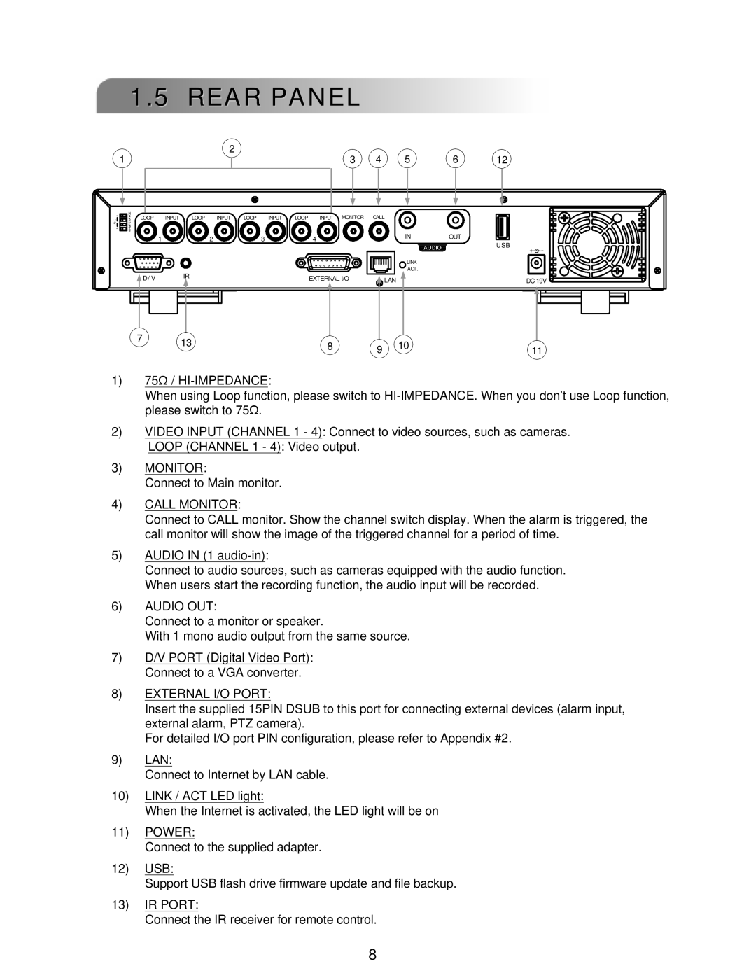
1)75Ω / HI-IMPEDANCE:
When using Loop function, please switch to
2)VIDEO INPUT (CHANNEL 1 - 4): Connect to video sources, such as cameras.
LOOP (CHANNEL 1 - 4): Video output.
3)MONITOR:
Connect to Main monitor.
4)CALL MONITOR:
Connect to CALL monitor. Show the channel switch display. When the alarm is triggered, the call monitor will show the image of the triggered channel for a period of time.
5)AUDIO IN (1
Connect to audio sources, such as cameras equipped with the audio function. When users start the recording function, the audio input will be recorded.
6)AUDIO OUT:
Connect to a monitor or speaker.
With 1 mono audio output from the same source.
7)D/V PORT (Digital Video Port): Connect to a VGA converter.
8)EXTERNAL I/O PORT:
Insert the supplied 15PIN DSUB to this port for connecting external devices (alarm input, external alarm, PTZ camera).
For detailed I/O port PIN configuration, please refer to Appendix #2.
9)LAN:
Connect to Internet by LAN cable.
10)LINK / ACT LED light:
When the Internet is activated, the LED light will be on
11)POWER:
Connect to the supplied adapter.
12)USB:
Support USB flash drive firmware update and file backup.
13)IR PORT:
Connect the IR receiver for remote control.
8