operating from the 3.3V rails and the 12V rail provide the necessary voltages. The following states determine the typical current consumption of the controller:
•State 1: During a hard reset
•State 2: During a drive stress test
•State 3: While sitting idle at the DOS prompt
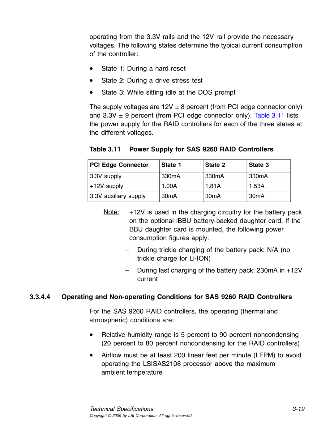
The supply voltages are 12V ± 8 percent (from PCI edge connector only) and 3.3V ± 9 percent (from PCI edge connector only). Table 3.11 lists the power supply for the RAID controllers for each of the three states at the different voltages.
Table 3.11 Power Supply for SAS 9260 RAID Controllers
PCI Edge Connector | State 1 | State 2 | State 3 |
|
|
|
|
3.3V supply | 330mA | 330mA | 330mA |
|
|
|
|
+12V supply | 1.00A | 1.81A | 1.53A |
|
|
|
|
3.3V auxiliary supply | 30mA | 30mA | 30mA |
|
|
|
|
Note: +12V is used in the charging circuitry for the battery pack on the optional iBBU
–During trickle charging of the battery pack: N/A (no trickle charge for
–During fast charging of the battery pack: 230mA in +12V current
3.3.4.4Operating and
For the SAS 9260 RAID controllers, the operating (thermal and atmospheric) conditions are:
•Relative humidity range is 5 percent to 90 percent noncondensing (20 percent to 80 percent noncondensing for the RAID controllers)
•Airflow must be at least 200 linear feet per minute (LFPM) to avoid operating the LSISAS2108 processor above the maximum ambient temperature
Technical Specifications |
Copyright © 2009 by LSI Corporation. All rights reserved.