LSISAS6160 SAS Switch
Revision History
Table of Contents
SAS Domain Manager Command Line Interface
Features
Chapter
Serial Attached Scsi and the SAS6160 Switch
LSISAS6160 Switch
LSISAS6160 Resource Management
Block Diagram of the LSISAS6160 Switch
SAS Phys, Ports, and Connectors
Link between Two Single SAS Phys
Narrow and Wide SAS Ports
SAS Connectors and Cabling
Mini SAS 4x Cable
Across the entire Zpsds
Minimize conflicts
Only the storage within its zone or zones
SAS Zoning Overview
Following figure shows a simple example of zoning
Groups and zone sets manually by using the SDM utility
Creating SAS Zones
Overview SAS Routing and Zoning
Configuration for Zoning Example
Connecting Devices to the SAS6160 Switch
Creating Zone Groups
Example 1, Multiple Servers and JBODs
Example 3, Multiple Servers and a Cascading Switch
Example 4, High Availability
Example 5, Large Data Storage Topology
Example 6, Cascaded Switches
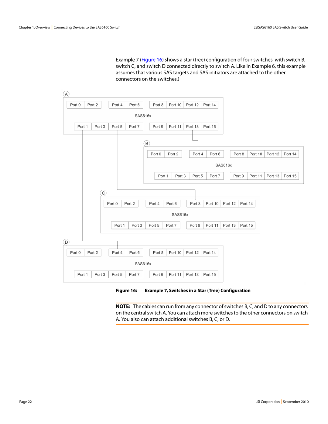
Example 7, Switches in a Star Tree Configuration
To interpret the LEDs on the switch
Unpacking the Switch
Identifying Switch Components
Carton contains the following items
Cables
Installing the SAS6160 Switch
SAS6160 Connectors
SAS6160 LEDs
Rack. These options are shown in the following figure
Mounting Shelf in a Rack
Connecting to a Host Changing the Default Static IP Address
Setting a Static IP Address
Using SDM-GUI
Exit SDM-GUI and power cycle the switch
Exit SDM-CLI and power cycle the switch
For example
Connecting SAS and Sata Hardware Safety Notices
1 FCC
Canada Mark Vcci Bsmi
5 CCC
Installation and Hardware Setup Safety Notices
SDM-GUI Accounts
Starting SDM-GUI
Options
Embedded SDM only supports a single domain
File, Server, and Help Menu Options
For zoning
Information is available to both admin and user accounts
Views Tab
View End Device Table
Alias Table
View Zone Groups
View Zone Groups
View Zone Sets
View Zone Sets
Node100, and so on
Domain Tab
This section, click the hyperlinks on the Domain tab
Alias Management
Domain. You also can also this command to delete aliases
View/Delete Aliases command
View/Delete Aliases
Box and clicking the Delete button
Connector Wizard
Zone set and the two associated zone groups
Group to communicate with each other
Check box and clicking the Delete button
Guide you through the configuration process
Maximum number of 248, the wizard displays an error message
Zone group to communicate with each other
Manually Configure Zone Groups Create Zone Group
Create Zone Group
Modify Zone Group
Time of activation. shows the View Zone Group window
View Zone Group
Delete Zone Group
Password
Maximum password length is 32 characters
Binary 0, as defined by the SAS 2.0 specification
Matrix
View Zone Set
View Zone Set window
Zone set
Modify Zone Set
Activate/Deactivate Zone Set
Activate/Deactivate Zone Set
Window and then clicking Delete
Delete Zone Set
Devices Tab
Device Tree and Properties Tab
Following figure shows the Properties tab
Selected device. In , the domain properties are shown
Properties Tab
Background loop
Environmentals Tab
Following figure shows the Attached Devices tab
Those connections
Attached Devices Tab
Selected expander
Following figure shows the Phys tab
Zone Group Tab
Zone Group Tab
Update Firmware
This tab contains the following commands
Successful update
Operations Tab
Reset Switch
Following figure shows the Enable/Disable/Reset window
Enable/Disable/Reset
Phys
Configure IP
As shown in the following figures
Command Usage Syntax
Command arguments
„ help command
SDM-CLI Commands
Help command
Domain focus domain name
„ passwd user
Passwd admin user
„ passwd admin
Exit
„ alias delete
„ show zonegroup
„ show alias
„ show phy
„ show zoneset
„ zonegroup delete single name
„ zonegroup add name sas addressaliasphy
„ zonegroup create name
„ zonegroup delete all noconfirm
„ zoneset add name zone group zone group
Set membership
„ zoneset activate name
„ zoneset create name
Sdmcli show alias
Sample Output for Show Command
„ zoneset passwd
Sdmcli show alias Calhoun
Sdmcli show device Calhoun
Show domain
Sdmcli show domain
Sdmcli show phy
Show phy
RA Routing Attributes VP Virtual PHY Zone Grp
Alias Phy Device Capabilities SAS Address Type
Sdmcli show phy Calhoun
Show phy alias
Zoning Active Zone Group Number
Zoning Inactive * phy may be assigned to a zone group
SDM-CLI Version SDM-D Version
Sdmcli show phy Lincoln01
Sdmcli show version
Show phy alias phy
Show zoneset data name Sdmcli show zoneset data ZoneOne
Sdmcli show zonegroup ZoneOne#001
Sdmcli show zoneset active
Show zonegroup name
Xip -i get avail
Xip -i 500062b15555557f get exp
Troubleshooting

