Chapter 1: Overview Connecting Devices to the SAS6160 Switch | LSISAS6160 SAS Switch User Guide |
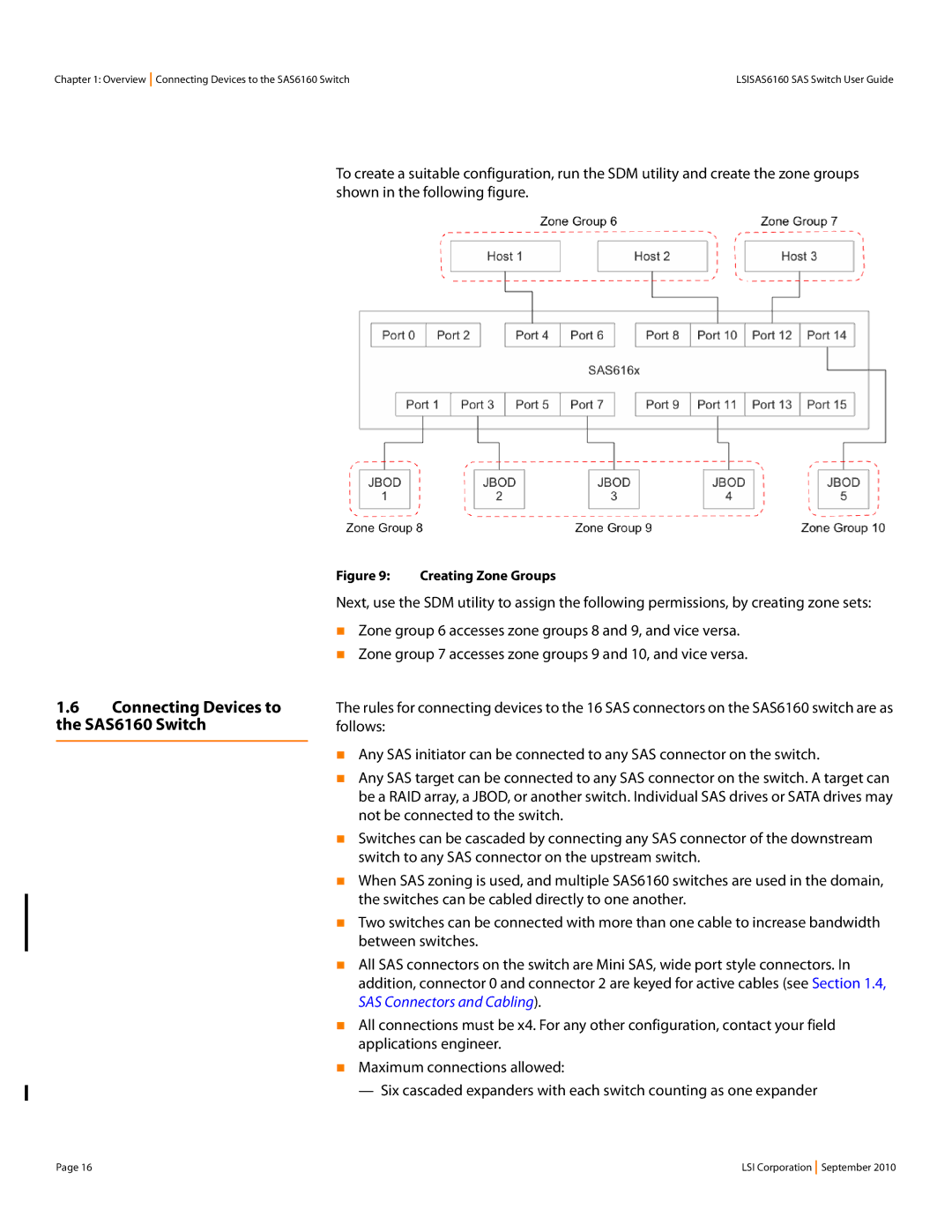
To create a suitable configuration, run the SDM utility and create the zone groups shown in the following figure.
1.6Connecting Devices to the SAS6160 Switch
Figure 9: Creating Zone Groups
Next, use the SDM utility to assign the following permissions, by creating zone sets:
Zone group 6 accesses zone groups 8 and 9, and vice versa.
Zone group 7 accesses zone groups 9 and 10, and vice versa.
The rules for connecting devices to the 16 SAS connectors on the SAS6160 switch are as follows:
Any SAS initiator can be connected to any SAS connector on the switch.
Any SAS target can be connected to any SAS connector on the switch. A target can be a RAID array, a JBOD, or another switch. Individual SAS drives or SATA drives may not be connected to the switch.
Switches can be cascaded by connecting any SAS connector of the downstream switch to any SAS connector on the upstream switch.
When SAS zoning is used, and multiple SAS6160 switches are used in the domain, the switches can be cabled directly to one another.
Two switches can be connected with more than one cable to increase bandwidth between switches.
All SAS connectors on the switch are Mini SAS, wide port style connectors. In addition, connector 0 and connector 2 are keyed for active cables (see Section 1.4, SAS Connectors and Cabling).
All connections must be x4. For any other configuration, contact your field applications engineer.
Maximum connections allowed:
— Six cascaded expanders with each switch counting as one expander
Page 16 | LSI Corporation September 2010 |