Model 117A4 Carrier Installation Instructions | Understanding Carriers | |
|
|
|
|
|
|
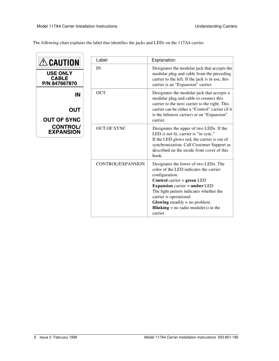
The following chart explains the label that identifies the jacks and LEDs on the 117A4 carrier.
Label | Explanation |
|
|
IN | Designates the modular jack that accepts the |
| modular plug and cable from the preceding |
| carrier to the left. If the jack is in use, this |
| carrier is an “Expansion” carrier. |
|
|
OUT | Designates the modular jack that accepts a |
| modular plug and cable to connect this |
| carrier to the next carrier to the right. This |
| carrier can be either a “Control” carrier (if it |
| is the leftmost carrier) or an “Expansion” |
| carrier. |
|
|
OUT OF SYNC | Designates the upper of two LEDs. If the |
| LED is not lit, carrier is “in sync.” |
| If the LED glows red, the carrier is out of |
| synchronization. Call Customer Support as |
| described on the inside front cover of this |
| book. |
|
|
CONTROL/EXPANSION | Designates the lower of two LEDs. The |
| color of the LED indicates the carrier |
| configuration: |
| Control carrier = green LED |
| Expansion carrier = amber LED |
| The light pattern indicates whether the |
| carrier is operational: |
| Glowing steadily = no problem. |
| Blinking = no radio module(s) in the |
| carrier. |
|
|
6 Issue 2 February 1999 | Model 117A4 Carrier Installation Instructions |