Model 117A4 Carrier Installation Instructions | Installing Multiple Carriers | |
|
|
|
|
|
|
Installing a Single Radio Module in Each Carrier
1Power down the carriers.
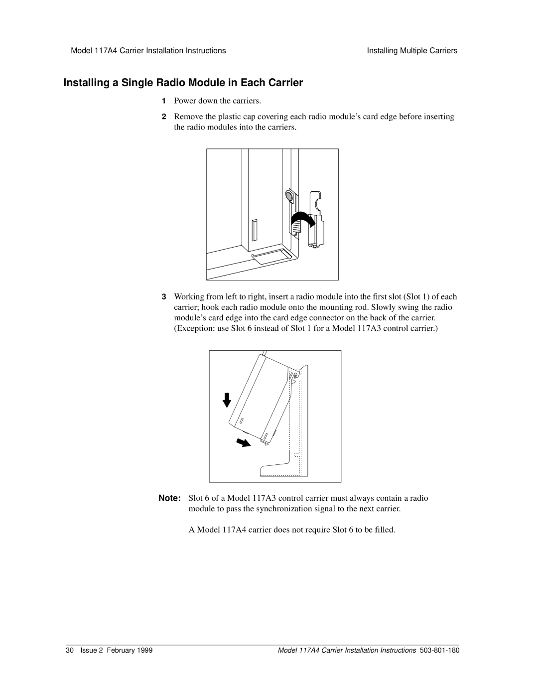
2Remove the plastic cap covering each radio module’s card edge before inserting the radio modules into the carriers.
3Working from left to right, insert a radio module into the first slot (Slot 1) of each carrier; hook each radio module onto the mounting rod. Slowly swing the radio module’s card edge into the card edge connector on the back of the carrier. (Exception: use Slot 6 instead of Slot 1 for a Model 117A3 control carrier.)
Note: Slot 6 of a Model 117A3 control carrier must always contain a radio module to pass the synchronization signal to the next carrier.
A Model 117A4 carrier does not require Slot 6 to be filled.
30 Issue 2 February 1999 | Model 117A4 Carrier Installation Instructions |
