Installing Multiple Carriers | Model 117A4 Carrier Installation Instructions | |
|
|
|
|
|
|
OUT OF SYNC | (red) | OUT OF SYNC | (red) | OUT OF SYNC | (red) | OUT OF SYNC | (red) |
| OUT OF SYNC | (red) |
CONTROL/ | (green) | CONTROL/ | (green) | (DIP switch |
| CONTROL/ | (green) |
| CONTROL/ | (green) |
EXPANSION |
| EXPANSION |
| in Slot 4 set to |
| EXPANSION |
|
| EXPANSION |
|
|
|
|
| Expansion) |
|
|
|
|
|
|
4 | T T | 4 | T T | 4 | T T | 4 | T T | 4 |
| T T |
CAUTION | CAUTIO | N | CAUTIO | N | CAUTIO | N |
CAUTION |
|
|
1 | 2 | 3 |
4 |
5 |
6 |
1 | 2 | 3 |
4 | 5 | 6 |
1 | 2 | 3 | 4 | 5 | 6 |
1 | 2 | 3 | 4 |
5 |
6 |
1 | 2 | 3 | 4 |
5 |
6 |
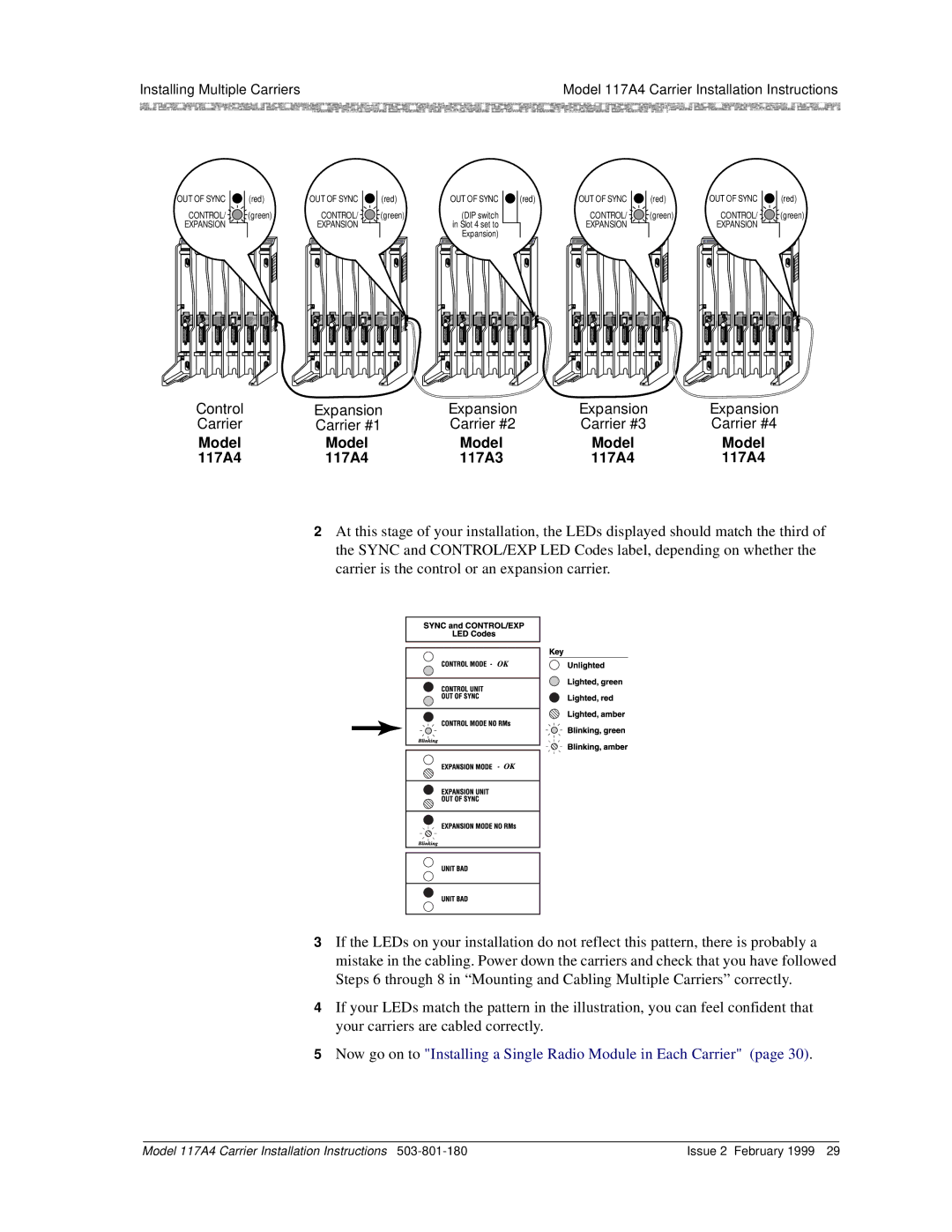
Control | Expansion | Expansion | Expansion | Expansion |
Carrier | Carrier #1 | Carrier #2 | Carrier #3 | Carrier #4 |
Model | Model | Model | Model | Model |
117A4 | 117A4 | 117A3 | 117A4 | 117A4 |
2At this stage of your installation, the LEDs displayed should match the third of the SYNC and CONTROL/EXP LED Codes label, depending on whether the carrier is the control or an expansion carrier.
3If the LEDs on your installation do not reflect this pattern, there is probably a mistake in the cabling. Power down the carriers and check that you have followed Steps 6 through 8 in “Mounting and Cabling Multiple Carriers” correctly.
4If your LEDs match the pattern in the illustration, you can feel confident that your carriers are cabled correctly.
5Now go on to "Installing a Single Radio Module in Each Carrier" (page 30).
Model 117A4 Carrier Installation Instructions | Issue 2 February 1999 29 |