Model 117A4 Carrier Installation Instructions | Installing Multiple Carriers | |
|
|
|
|
|
|
Installation Self Test with a Single Radio Module in Each Carrier
1Wait a few seconds after powering the carriers, then verify that the carriers’ OUT OF SYNC LEDs are not lit.
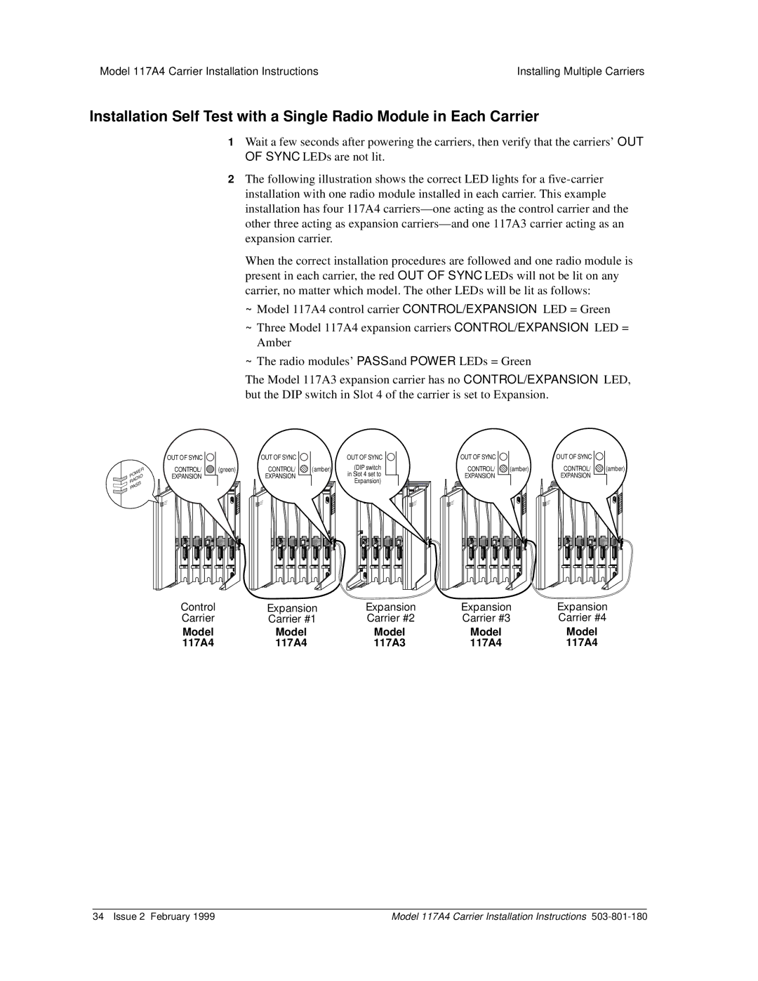
2The following illustration shows the correct LED lights for a
When the correct installation procedures are followed and one radio module is present in each carrier, the red OUT OF SYNC LEDs will not be lit on any carrier, no matter which model. The other LEDs will be lit as follows:
~Model 117A4 control carrier CONTROL/EXPANSION LED = Green
~Three Model 117A4 expansion carriers CONTROL/EXPANSION LED = Amber
~The radio modules’ PASS and POWER LEDs = Green
The Model 117A3 expansion carrier has no CONTROL/EXPANSION LED, but the DIP switch in Slot 4 of the carrier is set to Expansion.
POWER RADIO PASS
OUT OF SYNC |
| OUT OF SYNC |
| OUT OF SYNC |
| OUT OF SYNC |
| OUT OF SYNC |
|
CONTROL/ | (green) | CONTROL/ | (amber) | (DIP switch |
| CONTROL/ | (amber) | CONTROL/ | (amber) |
EXPANSION |
| EXPANSION |
| in Slot 4 set to |
| EXPANSION |
| EXPANSION |
|
| T T |
| T T | Expansion) | T T |
| T T |
| T T |
| ION |
| CAUTION |
| ION |
CAUT | CAUTION | CAUTION | CAUT |
|
2 | 3 | 4 | 5 | 6 | 2 | 3 | 4 | 5 | 6 | 1 | 2 | 3 | 4 | 2 | 3 | 4 | 5 | 6 | 2 | 3 | 4 | 5 | 6 |
Control | Expansion | Expansion | Expansion | Expansion |
Carrier | Carrier #1 | Carrier #2 | Carrier #3 | Carrier #4 |
Model | Model | Model | Model | Model |
117A4 | 117A4 | 117A3 | 117A4 | 117A4 |
34 Issue 2 February 1999 | Model 117A4 Carrier Installation Instructions |