Model 117A4 Carrier Installation Instructions | Understanding Carriers | |
|
|
|
|
|
|
Positioning Your Carrier(s)
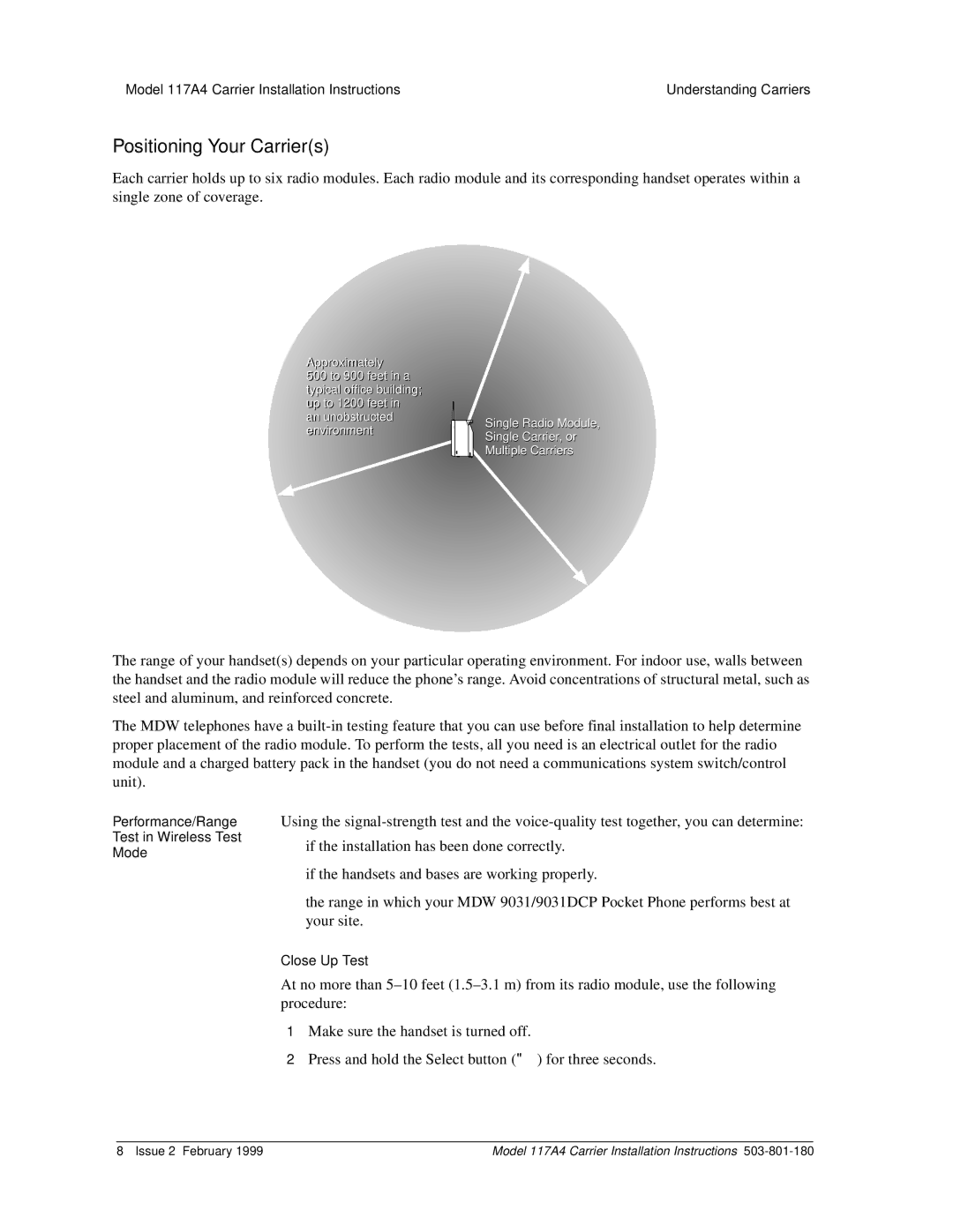
Each carrier holds up to six radio modules. Each radio module and its corresponding handset operates within a single zone of coverage.
Approximately
500 to 900 feet in a typical office building; up to 1200 feet in
an unobstructed environment
Single Radio Module, Single Carrier, or Multiple Carriers
The range of your handset(s) depends on your particular operating environment. For indoor use, walls between the handset and the radio module will reduce the phone’s range. Avoid concentrations of structural metal, such as steel and aluminum, and reinforced concrete.
The MDW telephones have a
Performance/Range
Test in Wireless Test
Mode
Using the
•if the installation has been done correctly.
•if the handsets and bases are working properly.
•the range in which your MDW 9031/9031DCP Pocket Phone performs best at your site.
Close Up Test
At no more than
1Make sure the handset is turned off.
2Press and hold the Select button (") for three seconds.
8 Issue 2 February 1999 | Model 117A4 Carrier Installation Instructions |