MDV455
Serial No
Warranty Verification
Contents
Safety Information
Cause the product and cart combination to overturn
Safety Information cont’d
Example of Antenna Grounding per National Electrical Code
Introduction
Playable Discs
DVD Player Upgrades
Playable Discs
Region Codes and Color Systems
General Information
Determining the best possible connection
Hookups
Before you begin
Remember
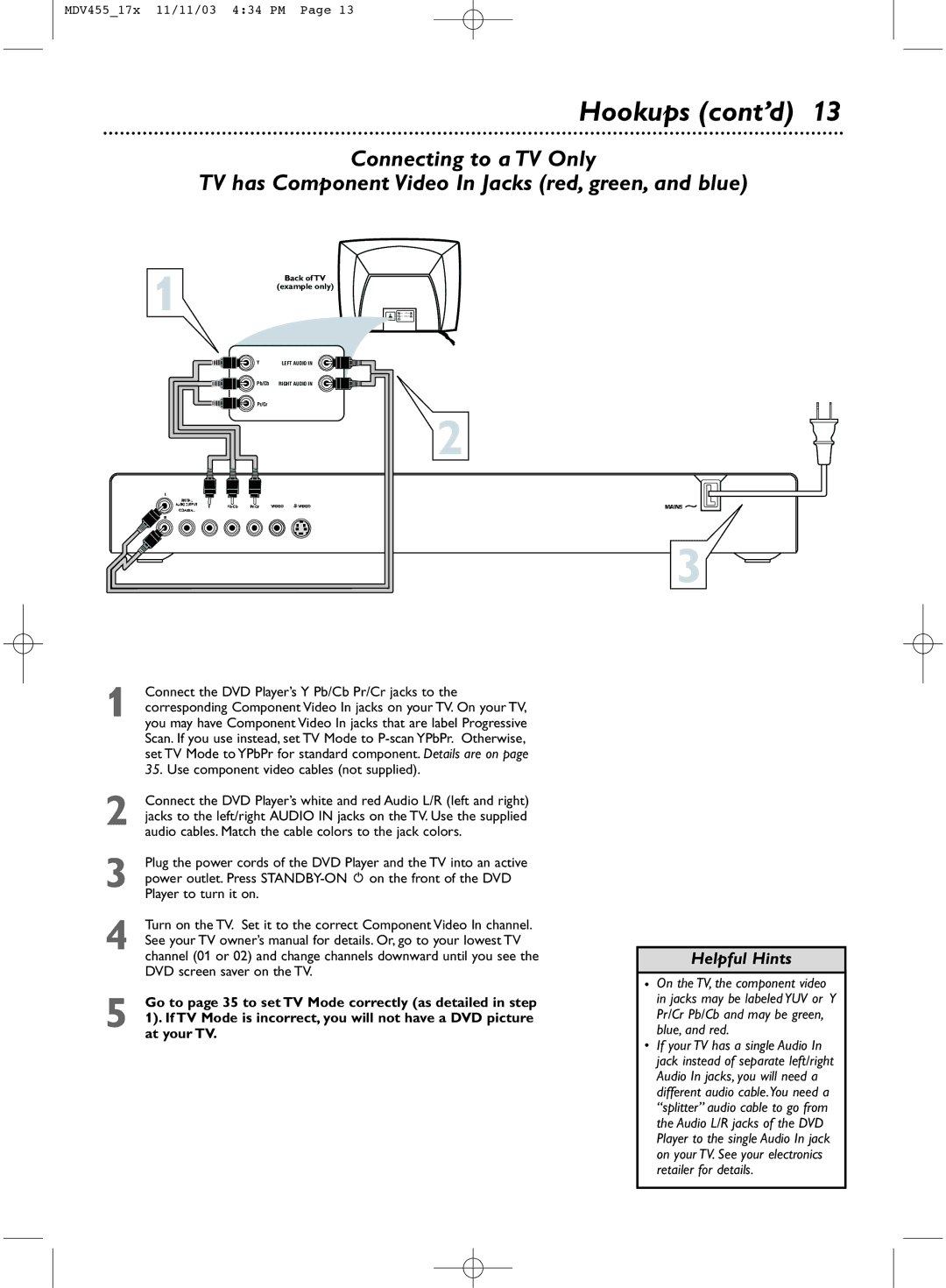
Hookups cont’d
Connecting to a TV Only TV has a yellow Video In jack
DVD Player and to the TV’s S-VIDEO In jack
Connecting to a TV Only TV has an S-Video In Jack
Connect the DVD Player’s Y Pb/Cb Pr/Cr jacks to
Has yellow markings
Connect the supplied video cable to the yellow Video jack
Set Spdif Output accordingly. Details are on
Quick Disc Playback
Remote Control Buttons
Front Panel
Rear Panel
Title/Disc menus
Title/Disc Menus, Chapter/Track Selection
Chapter/Track Selection
Slow Motion
Slow Motion, Fast Forward and Fast Reverse
Fast Forward and Fast Reverse
Still Picture/Frame-by-Frame Playback
Still Picture/Frame-by-Frame Playback,Time Search
Time Search
TV screen as in the DVD example below
Zoom/Reduce
Zoom/Reduce, Camera Angle
Camera Angle
Repeat
Repeat, Repeat A-B
Repeat A-B
Track,Title, or Disc ALL repeatedly
Audio will be selected. Press
DVD Audio Language
Press System Menu to remove the menus
Press 4 to select Subtitle, then press
DVD Subtitle Language
Press 4 to select Disc Menu, then press
DVD Disc Menu Language
Steps below
Parental Password
See
Parental level, see Press Stop 9 twice to stop DVD playback
Rating Explanations
Parental Levels
Press 4 to select Program. Press 2 to select Input Menu
Program not for Picture CD/MP3
Use the Number buttons on the remote to enter other
Correct Title/Chapter/Track number
DVD Video CD
Preview
Jpeg and MP3 Features
TV Display
General Setup Page will be selected. Press OK
Press System Menu while Disc play is stopped
TV Display will be selected. Press
Video Setup
TV Mode
TV Type,TV Mode
TV Type
Press System Menu to remove the menus
Downmix
Downmix, Dual Mono
Spdif Output
Reverb Mode
Equalizer EQ Type, Reverb Mode
Equalizer EQ Type
Display Language
Display Language, Closed Captions
Closed Captions
Screen Saver
Screen Saver, Angle Mark
Angle Mark
Press 4 to select Angle Mark, then press
DVD Player Defaults
Post DRC, DVD Player Defaults
Press 1 or 2 to select Speaker Setup Page, press OK or
Post DRC
Helpful Hints
No power
No picture
Distorted picture
Helpful Hints contd
Glossary
Specifications
Specifications, Language Codes
Language Codes
Renewed
Quick disc playback
Information Index

