CF-W5
For U.K This apparatus must be earthed for your safety
How to replace the fuse
Laser Safety Information
Page
Page
Contents
Specifications
Page
Page
Names and Functions of Parts
Mini Port Replicator Connector
Block Diagram
Diagnosis Procedure
Flow Chart
Troubleshooting
Outline of Post
Error Diagnosis by Checking Beep Signal Sound
Stuck key
02D0 System cache error Cache disabled
When you execute an automatic test
When you execute the enhancing test
Shift and left Shift keys
Operation of PC-Diagnostic Utility
PC-Diagnostic utility End method
Content of the setup is returned to the setting of the user
Selection of tested device
Test Item and Division of trouble
GPS
Wiring Connection Diagram
Disassembly instructions
Preparation
Before disassembly, be sure to perform the following steps
Removing the Keyboard
Preparation perform the .2.1. first
Removing the Top Case
Removing the HDD
Preparation perform the .2.1., 9.2.2. first
HDD
Removing the SW Board
Preparation perform the .2.1. to 9.2.3. first
FFC PAD FFC SW
Removing the Disc Cover
Removing the Touch Pad
PAD FFC
Removing the Speaker
Removing the LCD Knob
Removing the Solenoid
Removing the Main Board
Remove the DC-IN jack holder
Removing the Drive Unit
Removing the Wireless LAN Module
Removing the Antenna Board L,R
Removing the USB Board
Removing the Card Bus Ejector
Removing the Modem
Preparation perform the .2.1. to 9.2.4. and 9.2.11. first
Preparation perform the .2.1. to 9.2.3. and 9.2.11. first
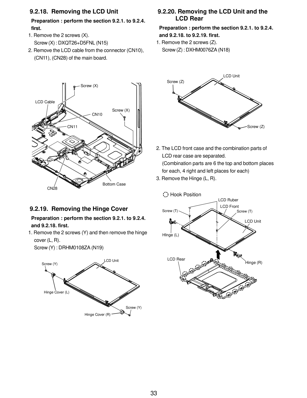
Removing the Hinge Cover
Removing the LCD Unit
Removing the LCD Unit and the LCD Rear
Preparation perform the .2.1. to 9.2.4. and 9.2.18. first
Removing the Wwan Antenna Board MAIN, SUB
Removing the Inverter Board
Removing the Wwan Board
Assembly of the LCD Front
Assembly knowhow of the LCD
Putting TP Flexible Protection Tape
Putting LCD Insulator
LCD
Putting LCD Side Dumpers
Assembly of the LCD Unit
Bold
Assembly of the LCD Dumper
Connecting LCD Cable
Assembly of the Inverter and Putting Inverter Tapes
Cable is processed to the LCD frame clamping Built-in order
Line processing LCD Cable
Putting Tapes of LCD Cable
Safety work
Putting LCD Rear Cushions
Assembly of the WM Cable
Putting Tapes for WM Cable
Assembly of the Wwan Board
Next
Setting Spacer CU on Antenna Cover
Assembly of the Hinge Cover L, R
Assembly of the LCD Rear
Putting tapes for Memory Sheet of top side
Assembly knowhow of the Main Board
Putting PET tapes
Assembly of the MDC Modem
Putting Main PW Sheet
Assembly of the Pcmcia Ejector
Assembly of the LAN Cable
Assembly of the DVD FFC
DVD FFC
Line processing LAN cable
Screw tightening of Main Board
DXQT2+D25FNL
Assembly of the W-LAN Module / Putting Memory Heat Sheet
Putting Sheets
Assembly of theMODEM Cable
Between cushion and addable Memory Processing 5mm 3mm
Assembly of the HDD FPC
Assembly of the W-LAN Sheet
HDD FPC
Setting the Main Board
Assembly of the DC-IN Cable
Boss B
Wlan SW
Assembly knowhow of the Top Case
Assembly of the DVD Cover
Assembly of theBreak Lever
Putting Disk Cover Sheet
Assembly of the Disk Cover Lock
Safety work Inserts under the rib
Assembly of the SW Board
Line processing Speaker Cable and putting Speaker Sheet
Assembly of the Speaker
Putting Hinge Buckup Sheet and LCD Knob Sheet etc
Assembly of the LCD Knob
Work
Assembly of the Touch Pad
Assembly of the Disk Cover
Disk angle cushion Screw
Order
Setting Antenna Board and Line processing
Assembly knowhow of the Bottom Case
Line processing HDD FPC
Assenbly of the Antenna Cover L
Treatment device
Putting Tape and Sheet
Do not run aground to the pin
Assembly knowhow of the Body
Setting LCD
Line processing LCD Cable bottom case side
Assembly of the Top Case
Setting Disk Cover
PET
DXQT2+E6FNL
DXQT26+D8FCL
Assembly of the Keyboard
Assembly of the Disk Cover and Antenna Cover R
Order
Setting Keyboard
Assembly of the Heat Spreader
Page
Tightening screw of Bottom Case
Setting Dimm Cover
Putting Sheet
Product back ratings signature board
Putting Labels
Assembly of the HDD / HDD Cover
Putting Tapes for Wwan Antenna Cable
Assembly of the Wwan Module
Screw tightening torque
Exploded View
Cabinet Section
SW6
REF. no
Accessories
Main Block Unit
Packing Material
LAN Switch Knob
Hinge Cover R
DFHR3F77ZA USB Cable FIX Sheet
CF-W5LWEZZBM REF. no and Area
Page
Page
Page
Page
Page
Page
Page
Ceramic Capacitor
Connector
Thermistor
Diode
LED
DEDRB081L20 Diode
FUSE, 2A
FUSE, 4A
IC, USB Power SW
IC, Power Management Switch
IC, Q-SWITCH
IC, FET Switch
Switch
IDUCTOR, Common Mode Filter
IC, Eeprom
IC, SPI Flash Memory
FET
Transistor
B1GBCFJN0037 Transistor
B1GBCFNL0017 Transistor B1GBCFNN0042
B1GFCFEN0003 Transistor
Resistor Array
DEARA8AJ103M Resistor Array
ERA3YEB203V RESISTOR, 1/16W, 20KΩ
ERA3YEB123V RESISTOR, 1/16W, 12KΩ
ERA3YEB243V RESISTOR, 1/16W, 24KΩ
ERA3YEB333V RESISTOR, 1/16W, 33KΩ
ERJ2GEJ100X
ERJ2GEJ101X
Page
ERJ2GEJ104X
ERJ2GEJ105X RESISTOR, 1/16W, 1MΩ
ERJ2GEJ106X RESISTOR, 1/16W, 10MΩ
ERJ2GEJ154X
ERJ2GEJ153X RESISTOR, 1/16W, 15KΩ
ERJ2GEJ201X
ERJ2GEJ203X RESISTOR, 1/16W, 20KΩ
ERJ2GEJ473X RESISTOR, 1/16W, 47KΩ
ERJ2GEJ472X
ERJ2GEJ474X
ERJ2GEJ510X
ERJ2RKD364X
ERJ2RKD244X
ERJ2RKF1000X
ERJ2RKF1001X RESISTOR, 1/16W, 1KΩ
ERJ2RKF5101X
Slide Switch
ERJ2RKF5102X RESISTOR, 1/16W, 51KΩ ERJ2RKF51R0X
ERJ2RKF54R9X
USB Connector
EVQPLDA15 Switch
Trance
Crystal Oscillator
IC, DC/DC Converter
DIP Switch
B1GBCFNN0042 Transistor
ERA3YEB303V RESISTOR, 1/16W, 30KΩ

![]() Screw (X)
Screw (X)![]() CN11
CN11![]()
![]()
![]() Hook Position
Hook Position