Important Information and Connector Information
Important Information, con’t
standard CD Audio Discs that conform to the Official Compact Disc Standards which is indicated by the![]() Symbol. It will also play most
Symbol. It will also play most
9.CD Audio Discs recorded in the MP3 Format will playback on the MVP851 except discs that contain
10.The MVP851 will Play Video CD Discs,
11.Compact Discs that are not round (e.g. Novelty discs with octagonal or heart shapes) will not play properly in the MVP851 and should not be tried, as possible damage may occur.
12.In order to view the Progressive Scan Video Output of the MVP851, the TV/Monitor connected to it must be capable of displaying a Progressive Picture and setup to display the Progressive Signal.
13.CAUTION: DO NOT ACTIVATE the MVP851 DVD Player’s Progressive Video Display Mode unless you are certain that the TV/Monitor connected to the MVP851 is capable of displaying a Progressive Scan Signal. Failure to do so could result in possible Damage to the TV/Monitor.
14.The Digital Audio
15.Some Multichannel
16.The
17.Certain Dolby Digital and DTS Encoded Discs display their own unique Audio Mode Selection menu, every time the disc is loaded into the player. If you do not make a choice from this menu, the disc will revert to its default Audio Mode when play is started.
18.The MVP851 basic transport functions may also be controlled by using the Remote Control that comes with a McIntosh Control Center or Preamplifier. McIntosh Keypads can also be used to remotely control the basic transport functions of the MVP851. Remote Controls of certain McIntosh Control Centers or Preamplifiers also have additional
Important Information, con’t
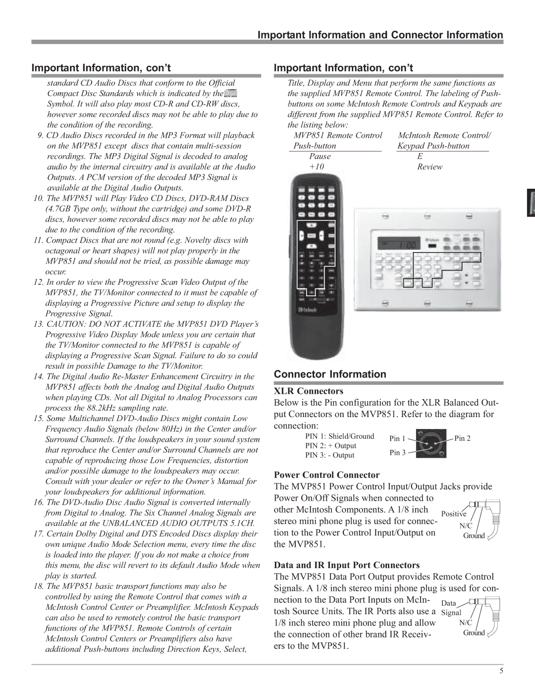
Title, Display and Menu that perform the same functions as the supplied MVP851 Remote Control. The labeling of Push- buttons on some McIntosh Remote Controls and Keypads are different from the supplied MVP851 Remote Control. Refer to the listing below:
MVP851 Remote Control
Pause +10
Connector Information
XLR Connectors
Below is the Pin configuration for the XLR Balanced Out- put Connectors on the MVP851. Refer to the diagram for connection:
PIN 1: Shield/Ground | Pin 1 | Pin 2 | |
PIN 2: + Output | |||
Pin 3 |
| ||
PIN 3: - Output |
| ||
|
|
Power Control Connector
The MVP851 Power Control Input/Output Jacks provide | ||
Power On/Off Signals when connected to |
| |
other McIntosh Components. A 1/8 inch | Positive | |
stereo mini phone plug is used for connec- | ||
N/C | ||
tion to the Power Control Input/Output on | ||
Ground | ||
| ||
the MVP851. |
| |
Data and IR Input Port Connectors
The MVP851 Data Port Output provides Remote Control Signals. A 1/8 inch stereo mini phone plug is used for con-
nection to the Data Port Inputs on McIn- | Data |
|
|
|
| ||
|
| ||
tosh Source Units. The IR Ports also use a | Signal | ||
1/8 inch stereo mini phone plug and allow | N/C | ||
the connection of other brand IR Receiv- | Ground | ||
ers to the MVP851. |
|
|
|
5