MVP851 Rear Panel Connections
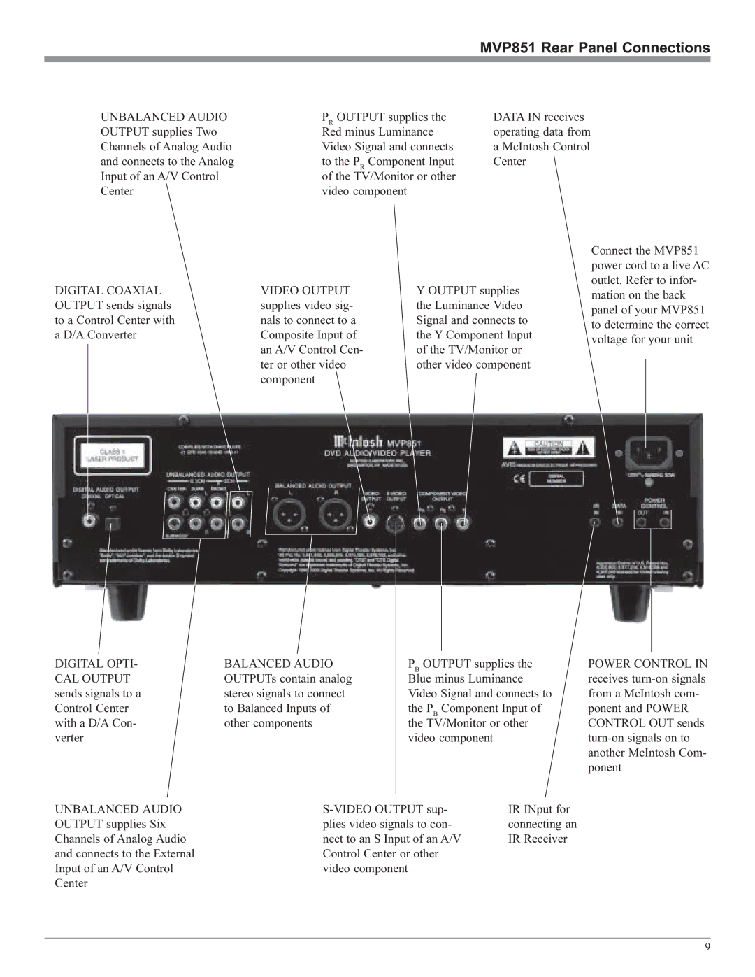
UNBALANCED AUDIO OUTPUT supplies Two Channels of Analog Audio and connects to the Analog Input of an A/V Control Center
PR OUTPUT supplies the | DATA IN receives |
Red minus Luminance | operating data from |
Video Signal and connects | a McIntosh Control |
to the PR Component Input | Center |
of the TV/Monitor or other |
|
video component |
|
DIGITAL COAXIAL OUTPUT sends signals to a Control Center with a D/A Converter
VIDEO OUTPUT supplies video sig- nals to connect to a Composite Input of an A/V Control Cen- ter or other video component
Y OUTPUT supplies the Luminance Video Signal and connects to the Y Component Input of the TV/Monitor or other video component
Connect the MVP851 power cord to a live AC outlet. Refer to infor- mation on the back panel of your MVP851 to determine the correct voltage for your unit
DIGITAL OPTI- CAL OUTPUT sends signals to a Control Center with a D/A Con- verter
BALANCED AUDIO OUTPUTs contain analog stereo signals to connect to Balanced Inputs of other components
PB OUTPUT supplies the Blue minus Luminance Video Signal and connects to the PB Component Input of the TV/Monitor or other video component
POWER CONTROL IN receives
UNBALANCED AUDIO OUTPUT supplies Six Channels of Analog Audio and connects to the External Input of an A/V Control Center
IR INput for | |
plies video signals to con- | connecting an |
nect to an S Input of an A/V | IR Receiver |
Control Center or other |
|
video component |
|
9