Using 518 for Mastering and Multimedia | 34 |
|
|
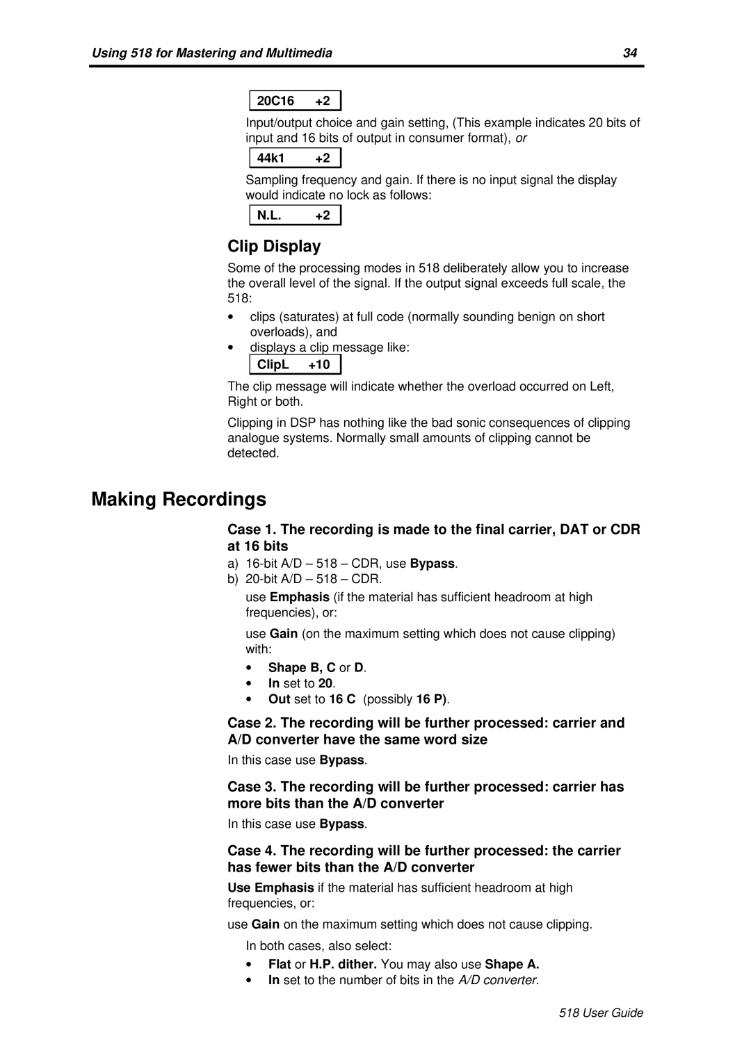
20C16 +2
Input/output choice and gain setting, (This example indicates 20 bits of input and 16 bits of output in consumer format), or
44k1 +2
Sampling frequency and gain. If there is no input signal the display would indicate no lock as follows:
N.L. +2
Clip Display
Some of the processing modes in 518 deliberately allow you to increase the overall level of the signal. If the output signal exceeds full scale, the 518:
∙clips (saturates) at full code (normally sounding benign on short overloads), and
∙displays a clip message like:
ClipL +10
The clip message will indicate whether the overload occurred on Left,
Right or both.
Clipping in DSP has nothing like the bad sonic consequences of clipping analogue systems. Normally small amounts of clipping cannot be detected.
Making Recordings
Case 1. The recording is made to the final carrier, DAT or CDR at 16 bits
a)
b)
use Emphasis (if the material has sufficient headroom at high frequencies), or:
use Gain (on the maximum setting which does not cause clipping) with:
∙Shape B, C or D.
∙In set to 20.
∙Out set to 16 C (possibly 16 P).
Case 2. The recording will be further processed: carrier and
A/D converter have the same word size
In this case use Bypass.
Case 3. The recording will be further processed: carrier has more bits than the A/D converter
In this case use Bypass.
Case 4. The recording will be further processed: the carrier has fewer bits than the A/D converter
Use Emphasis if the material has sufficient headroom at high frequencies, or:
use Gain on the maximum setting which does not cause clipping.
In both cases, also select:
∙Flat or H.P. dither. You may also use Shape A.
∙In set to the number of bits in the A/D converter.
518 User Guide
