5-2. Blowing Out Inside Of Unit
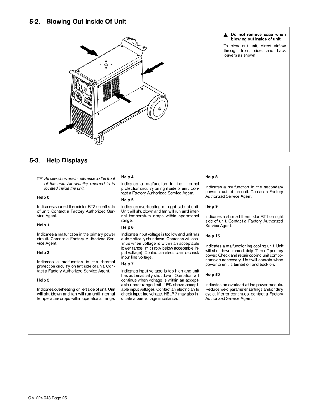
Y Do not remove case when blowing out inside of unit.
To blow out unit, direct airflow through front, side, and back louvers as shown.
5-3. Help Displays
. All directions are in reference to the front | Help 4 | Help 8 | |
of the unit. All circuitry referred to is | Indicates a malfunction in the thermal | Indicates a malfunction in the secondary | |
located inside the unit. | protection circuitry on right side of unit. Con- | ||
| tact a Factory Authorized Service Agent. | power circuit of the unit. Contact a Factory | |
Help 0 | Authorized Service Agent. | ||
Help 5 | |||
|
| ||
Indicates shorted thermistor RT2 on left side | Indicates overheating on right side of unit. | Help 9 | |
of unit. Contact a Factory Authorized Ser- | Unit will shutdown and fan will run until inter- |
| |
vice Agent. | nal temperature drops within operational | Indicates a shorted thermistor RT1 on right | |
Help 1 | range. | side of unit. Contact a Factory Authorized | |
Help 6 | Service Agent. | ||
|
| ||
Indicates a malfunction in the primary power | Indicates input voltage is too low and unit has | Help 15 | |
circuit. Contact a Factory Authorized Ser- | automatically shut down. Operation will con- | ||
| |||
vice Agent. | tinue when voltage is within an acceptable | Indicates a malfunctioning cooling unit. Unit | |
| lower range limit (15% below acceptable in- | ||
| will shut down immediately. Turn off primary | ||
Help 2 | put voltage). Contact an electrician to check | ||
power. Check and repair cooling unit compo- | |||
| input line voltage. | ||
Indicates a malfunction in the thermal | nents as necessary. Unit will operate when | ||
Help 7 | |||
power to unit is turned off and back on. | |||
protection circuitry on left side of unit. Con- | |||
|
| ||
tact a Factory Authorized Service Agent. | Indicates input voltage is too high and unit | Help 50 | |
| has automatically shut down. Operation will | ||
Help 3 | continue when voltage is within an accept- |
| |
| able upper range limit (15% above accept- | Indicates an overload at the power module. | |
Indicates overheating on left side of unit. Unit | able input voltage). Contact an electrician to | Reduce weld parameter settings and/or duty | |
will shutdown and fan will run until internal | check input line voltage. HELP 7 may also in- | cycle. If error continues, contact a Factory | |
temperature drops within operational range. | dicate a bus voltage imbalance. | Authorized Service Agent. | |
|
|
|