(3)Removing the expansion circuit boards (printer/network scanner/ network interface)
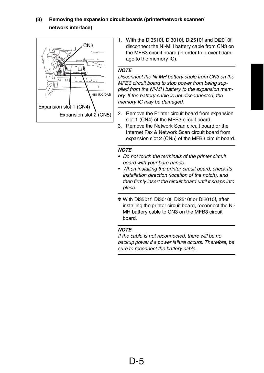
CN3 |
4514U010AB |
Expansion slot 1 (CN4) |
Expansion slot 2 (CN5) |
1.With the Di3510f, Di3010f, Di2510f and Di2010f, disconnect the
NOTE
Disconnect the
2.Remove the Printer circuit board from expansion slot 1 (CN4) of the MFB3 circuit board.
3.Remove the Network Scan circuit board or the Internet Fax & Network Scan circuit board from expansion slot 2 (CN5) of the MFB3 circuit board.
NOTE
•Do not touch the terminals of the printer circuit board with your bare hands.
•When installing the printer circuit board, check its installation direction (location of the notch), and then firmly insert the circuit board until it snaps into place.
✽With Di3501f, Di3010f, Di2510f or Di2010f, after installing the printer circuit board, reconnect the Ni- MH battery cable to CN3 on the MFB3 circuit board.
NOTE
If the cable is not reconnected, there will be no backup power if a power failure occurs. Therefore, be sure to reconnect the battery cable.