DX-TL950E
Features
Built-in duplex 9 channel multiplexer
Recording
Network
Ease of use
Auto set-up
Protect the Power Cord
When not in use always turn OFF the Main switch
Mains Lead Connection
Contents
60-63
65,66
67-71
72,73
Flowchart for connection and settings
Flowchart
Auto SET UP
Setting other various functions
Setting the motion detection
Setting the timer recording
Timer recording is executed/completed
Major operations and their functions
Emergency indicator
Lock indicator
Analogue OUT connectors
Front View Inside of the door
Alarm Interrupt button
SET UP button
Major operations and their functions
Search button
Main switch
Video OUT connectors
Camera in connectors
Camera OUT connectors
RS-232C connector
Ethernet connector
Connecting to Cctv camera, monitor, sensor
Connections
Connecting with analog video recorder
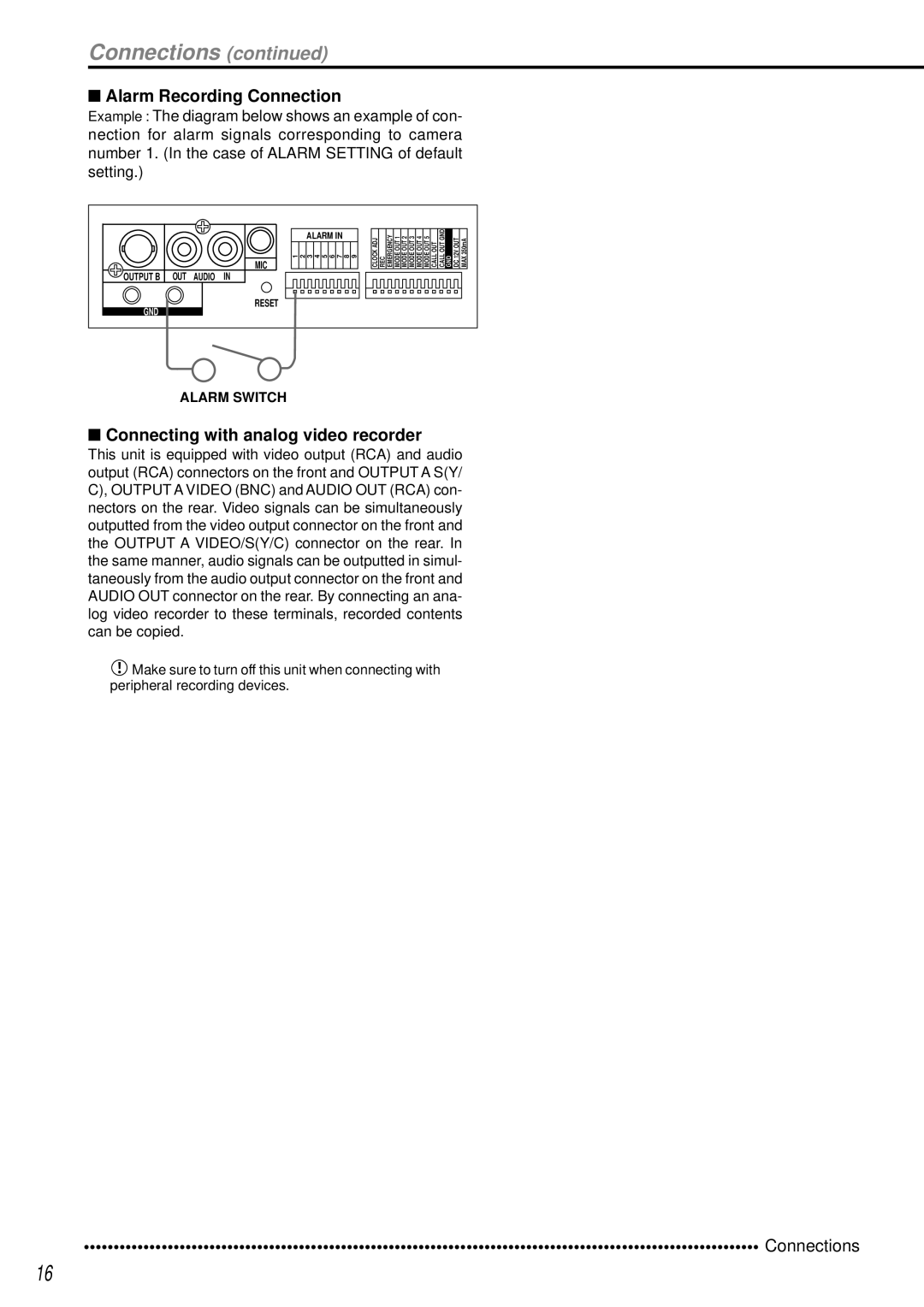
Alarm Recording Connection
Connections
Auto SET UP
Turn the Shuttle ring clockwise
Auto SET UP / Initial settings
HDD Setting
When the setting is complete, press the Power button
Initialization
Basic Operations
Menu settings
Multiplexer functions
Daylight SAVING/DAYLIGHT Setting
Default SUN, LAST, MAR
Time Date Adjust
Basic Operations
Present time display
Basic manual recording
Recorded capacity display function
Short
SUPER, HIGH, STDSTANDARD, BASIC, Long
Long
Basic playback
Back repeatedly see HDD Repeat PLAY,
To change HDD or Compact Flash Card playback device
Press the Play button
Basic search
Time Date Search
To pause playback, press the Pause button
To stop playback, press the Stop button
For playback, see Various playback func- tions, pages 65,66
Language Selection
English , Francais , Deutsch
Españ OL, PyCCKNN, Italiano
Menu Setting
Menu functions
Main Menu
SUB Menu
SET UP
Initial SET UP/INFORMATION HDD Settings
Menu functions
Main Menu SUB Menu
REC/STOP + Power button
Copy Menu
Search Selection Menu
Time Date Adjust
Display Mode
Camera TITLE/MEMO Setting
Clock Location Setting
Camera TITLE/MEMO Setting screen appears
Display returns to the Camera TITLE/MEMO Setting screen
Repeat steps 2 ~ 6 to input Counter in the camera number
Appears in reversed color on the very left of the string
Duplex Mode Display
Setting default Bottom
Plexer can also be found on see
Camera number button operations
SPLIT/SEQUENCE button operations
Available modes
MPX Display Settings
Zoom
MPX Display Settings
SPLIT4 Screen Setting
SPLIT9 Screen Setting
For the SPLIT9 Screen SETTING, SPLIT9 screen can be set
Interlace
Sequence Setting
3 , 4 , 5 , 6 , 7
Detection Mask Setting
Setting default 3 , 4 , 5 , 6 , 7 , 8
Selection Camera Number
Nected camera, are set
Motion Detection Settings
Test Mode
Sensitivity
Motion Threshold
Settings concerning normal recording and alarm recording
Ing pre-alarm recording, see
When setting the camera selection during alarm recording
Alarm Setting
About alarm recording
Record Settings
Picture quality for normal recording pages 22,23
Alarm REC Duration
PRE Alarm REC
Recording time during alarm recording can be set
Pre-alarm recording can be set
Timer Program
Timer Program Settings
Structure of the Timer Program screen
Press the Timer button
Timer Program Settings
Holiday Setting
Cerning recording mode settings, see pages 22,23
Overlapping Timer settings
HDD Settings HDD Repeat REC MAIN/HDD Repeat REC SUB
Setting default OFF
HDD Repeat Play
IM-CHECK Play
Initial SET UP/INFORMATION
Sequential Play
Audio Recording
Single screen sequential playback starts
KEY Sound
Rear Terminal Settings Mode OUT 1 ~ Mode OUT
Buzzer
Setting of Device default Main
Setting of Remain HDD default 10%
Call OUT Settings
Remain HDD
Communication Port Settings
RS-232C
HDD Main FULL/HDD SUB Full
Emergency REC Duration
Ethernet
Settings
Mail Address
Service Port Setting
Alarm Notification Setting
INFORMATION/SERVICE
INFORMATION/SERVICE 1/2
INFORMATION/SERVICE 2/2
Setting is confirmed and stops flashing
Menu screen settings are reset
Reset to Factory Settings Menu screen settings are reset
Data Clear
Password Lock
Password
Simple Lock
To unlock the Password
Input the Password entered in First in Second
To unlock the Password for level Press the SET UP button
Repeat steps 2-2 ~ 2-4 to set level 2 and level
Changing from Password Lock mode to Simple Lock mode
To lock the Password only level1 to level
To change the Password
Press the Warning Reset button
Quick Settings
To update menu settings of this unit
To save menu settings of this unit to a Compact Flash Card
Quick Settings screen appears
Setting
Operation examples
Operation example
Operation
This example uses the holiday setting
HDD Settings screen setting see pages 47,48
Holiday Setting 31/12, 01/01, 02/01, 03/01
Camera number 1 ~ Input title
REC Mode C screen setting see
Alarm Setting C screen setting see
Record Setting C screen setting see
Operation examples
REC Mode D screen setting see
Record Setting D screen setting see
Record Setting C
Alarm Setting D
PRE Alarm Recordings
Pre-alarm recording
Various recordings
Emergency Recordings
Various playback functions
Simultaneous playback during recording
Press the REV. Play Reverse Playback button
Search Selection
Various search
Time Date Search
Index SEARCH/ALARM Index Search
Various search
Press the Search button
Playback the search result
Alarm Skip Search In the case of forward direction
Alarm Skip Search
To clear the search screen, press the Search button twice
Alarm List Search
To clear the alarm list, erase the data
Press either the Play REV. Play or Pause button
START/END Search
Search screen selected in previous Search Type appears
Menu changes to Restore when CFC Main HDD is selected
Making Copy/Restore
An end. Be careful
Copying from unit to videotape
Back see Sequential PLAY,
Video Cord Audio Cord
Analogue Video Cassette Recorder
Power failure compensation circuit
Power failure reset recording
HDD Setting
Other convenient functions
Points to be aware of regarding Mirror mode
Points to be aware of regarding Partition mode
Partition Size setting appears on the Initialization screen
PARTITION/PARTITION Size
Covert Camera Setting
Alarm Display
Covert Camera Setting screen appears
Other convenient functions
Authentication
Communications by Web Browser
Communications by Web Browser
Personal computer product requirements
Welcome
Communications by Web Browser
Live monitor
Stop
Playback
Alarm Search
User maintenance
Time Search
Select the date and time and click Search
Log out
Covert Camera Setting
Change log in user
Logged in user is changed and the Welcome screen appears
Recording time table
Continuous recording time table
HDD continuous recording time for 250GB drive
Without Audio recording
Recording time table
Compact Flash Card continuous recording time for 64MB
Troubleshooting
Description of problem Please consult the following
Troubleshooting
Detection Mask Setting ?
Main
Image Modified
Glossary
Glossary
Specifications
Connectors
GND
Call OUT/CALL OUT GND