USING WITH THE PERSONAL COMPUTER
CONNECTING TO A PERSONAL COMPUTER
A personal computer that has an
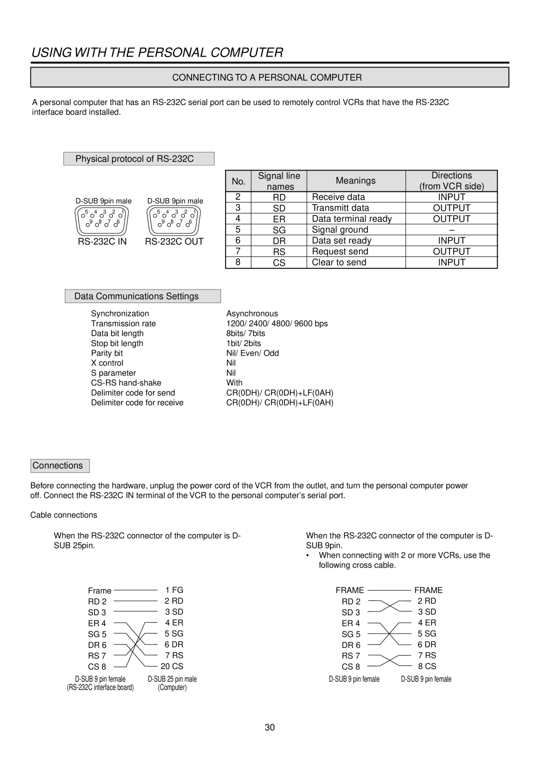
Physical protocol of RS-232C
5 | 4 | 3 | 2 | 1 | 5 | 4 |
| 3 | 2 | 1 |
9 | 8 | 7 |
| 6 |
| 9 | 8 | 7 |
| 6 |
Data Communications Settings
Synchronization
Transmission rate
Data bit length
Stop bit length
Parity bit
X control
S parameter
Delimiter code for send
Delimiter code for receive
No. | Signal line | Meanings | Directions | |
names | (from VCR side) | |||
|
| |||
2 | RD | Receive data | INPUT | |
3 | SD | Transmitt data | OUTPUT | |
4 | ER | Data terminal ready | OUTPUT | |
5 | SG | Signal ground | – | |
6 | DR | Data set ready | INPUT | |
7 | RS | Request send | OUTPUT | |
8 | CS | Clear to send | INPUT |
Asynchronous
1200/ 2400/ 4800/ 9600 bps 8bits/ 7bits
1bit/ 2bits
Nil/ Even/ Odd Nil
Nil
With
CR(0DH)/ CR(0DH)+LF(0AH) CR(0DH)/ CR(0DH)+LF(0AH)
Connections
Before connecting the hardware, unplug the power cord of the VCR from the outlet, and turn the personal computer power off. Connect the
Cable connections
1When the
2When the
•When connecting with 2 or more VCRs, use the following cross cable.
Frame | 1 FG | FRAME | FRAME |
RD 2 | 2 RD | RD 2 | 2 RD |
SD 3 | 3 SD | SD 3 | 3 SD |
ER 4 | 4 ER | ER 4 | 4 ER |
SG 5 | 5 SG | SG 5 | 5 SG |
DR 6 | 6 DR | DR 6 | 6 DR |
RS 7 | 7 RS | RS 7 | 7 RS |
CS 8 | 20 CS | CS 8 | 8 CS |
(Computer) |
|
|
30