CONTROL INPUT/OUTPUT SIGNALS AND CIRCUITS
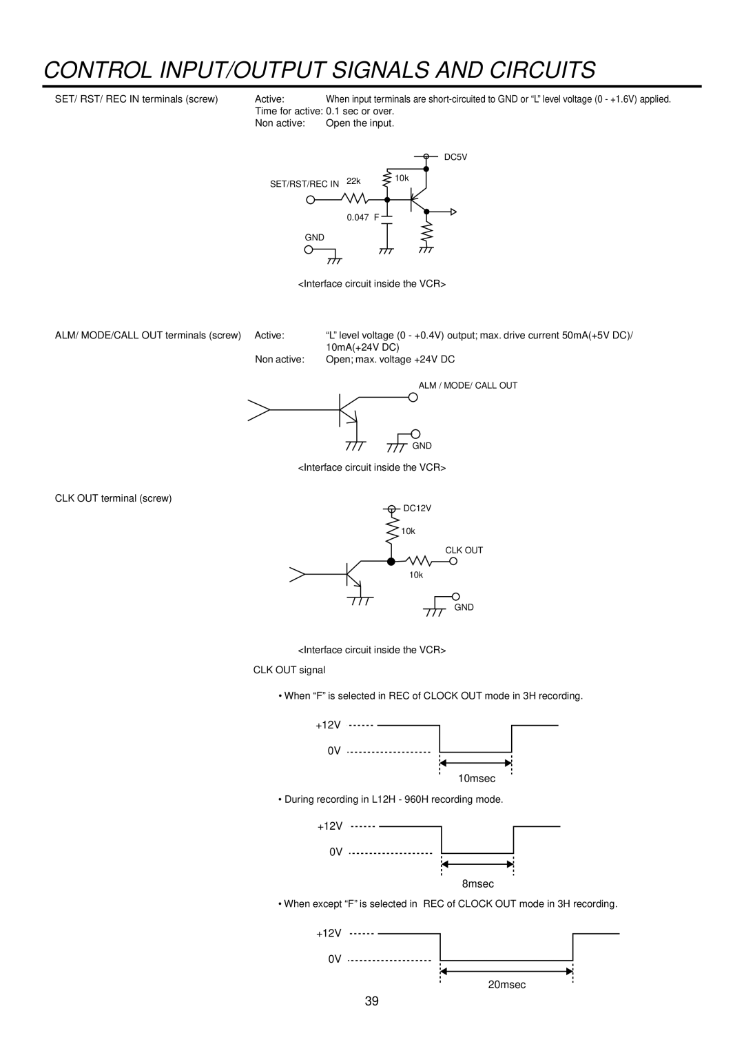
2SET/ RST/ REC IN terminals (screw)
Active: | When input terminals are |
Time for active: 0.1 sec or over. | |
Non active: | Open the input. |
|
| DC5V |
SET/RST/REC IN 22kΩ | 10kΩ | |
| ||
| 0.047∝ F |
|
| GND |
|
<Interface circuit inside the VCR> | ||
2ALM/ MODE/CALL OUT terminals (screw) Active: | “L” level voltage (0 - +0.4V) output; max. drive current 50mA(+5V DC)/ | |
| 10mA(+24V DC) | |
Non active: | Open; max. voltage +24V DC | |
ALM / MODE/ CALL OUT
GND
<Interface circuit inside the VCR>
2CLK OUT terminal (screw)
DC12V
10kΩ
CLK OUT
10kΩ
GND
<Interface circuit inside the VCR> CLK OUT signal
• When “F” is selected in REC of CLOCK OUT mode in 3H recording.
+12V
0V
10msec
•During recording in L12H - 960H recording mode.
+12V
0V
8msec
• When except “F” is selected in REC of CLOCK OUT mode in 3H recording.
+12V
0V
20msec
39