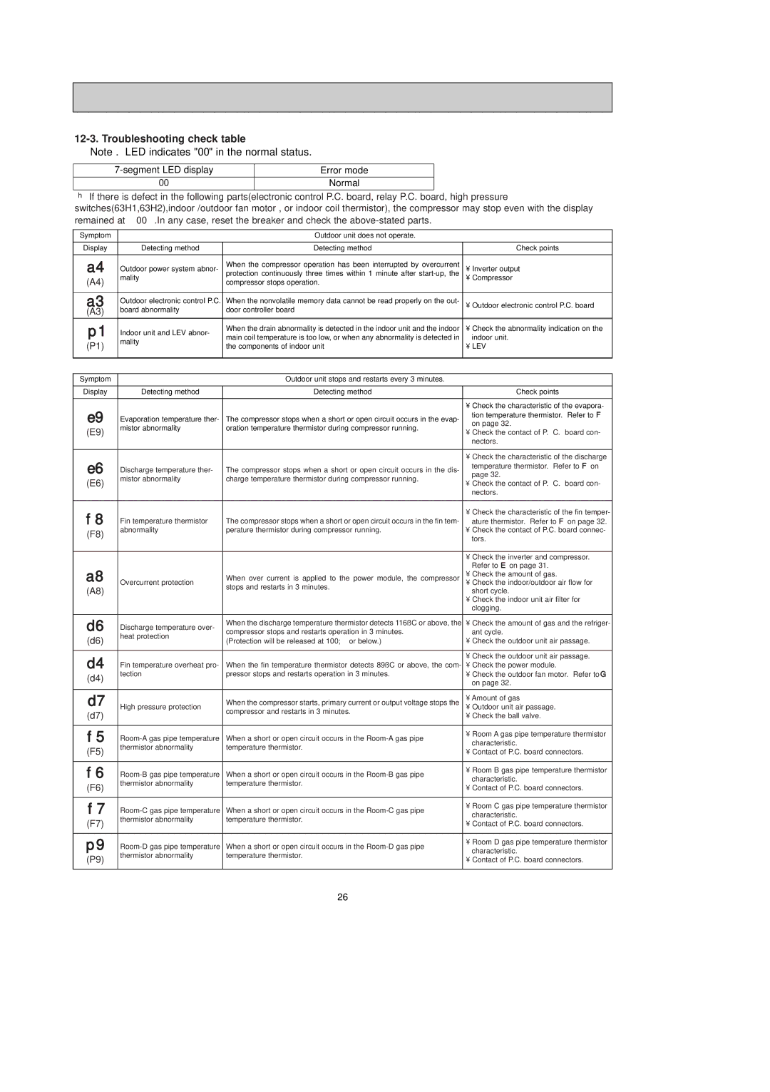
12-3. Troubleshooting check table
Note . LED indicates "00" in the normal status.
Error mode | |
00 | Normal |
❈If there is defect in the following parts(electronic control P.C. board, relay P.C. board, high pressure switches(63H1,63H2),indoor /outdoor fan motor , or indoor coil thermistor), the compressor may stop even with the display remained at “ 00 “.In any case, reset the breaker and check the
Symptom |
| Outdoor unit does not operate. |
| |
|
|
|
| |
Display | Detecting method | Detecting method | Check points | |
|
|
|
| |
a4 | Outdoor power system abnor- | When the compressor operation has been interrupted by overcurrent | • Inverter output | |
(A4) | mality | protection continuously three times within 1 minute after | • Compressor | |
| compressor stops operation. |
| ||
|
|
|
| |
a3 | Outdoor electronic control P.C. | When the nonvolatile memory data cannot be read properly on the out- | • Outdoor electronic control P.C. board | |
(A3) | board abnormality | door controller board | ||
| ||||
p1 | Indoor unit and LEV abnor- | When the drain abnormality is detected in the indoor unit and the indoor | • Check the abnormality indication on the | |
main coil temperature is too low, or when any abnormality is detected in | indoor unit. | |||
(P1) | mality | |||
the components of indoor unit | • LEV | |||
| ||||
|
|
|
| |
|
|
|
| |
Symptom |
| Outdoor unit stops and restarts every 3 minutes. |
| |
|
|
|
| |
Display | Detecting method | Detecting method | Check points | |
|
|
|
| |
|
|
| • Check the characteristic of the evapora- | |
e9 | Evaporation temperature ther- | The compressor stops when a short or open circuit occurs in the evap- | tion temperature thermistor. Refer to F | |
(E9) | mistor abnormality | oration temperature thermistor during compressor running. | on page 32. | |
• Check the contact of P. C. board con- | ||||
|
| |||
|
|
| nectors. | |
|
|
|
| |
|
|
| • Check the characteristic of the discharge | |
e6 | Discharge temperature ther- | The compressor stops when a short or open circuit occurs in the dis- | temperature thermistor. Refer to F on | |
(E6) | mistor abnormality | charge temperature thermistor during compressor running. | page 32. | |
• Check the contact of P. C. board con- | ||||
|
| |||
|
|
| nectors. | |
|
|
|
| |
f8 |
|
| • Check the characteristic of the fin temper- | |
Fin temperature thermistor | The compressor stops when a short or open circuit occurs in the fin tem- | ature thermistor. Refer to F on page 32. | ||
(F8) | abnormality | perature thermistor during compressor running. | • Check the contact of P.C. board connec- | |
|
| tors. | ||
|
|
| ||
|
|
|
| |
|
|
| • Check the inverter and compressor. | |
|
|
| Refer to E on page 31. | |
a8 | Overcurrent protection | When over current is applied to the power module, the compressor | • Check the amount of gas. | |
(A8) | stops and restarts in 3 minutes. | • Check the indoor/outdoor air flow for | ||
| short cycle. | |||
|
| |||
|
|
| • Check the indoor unit air filter for | |
|
|
| clogging. | |
|
|
|
| |
d6 | Discharge temperature over- | When the discharge temperature thermistor detects 116˚C or above, the | • Check the amount of gas and the refriger- | |
compressor stops and restarts operation in 3 minutes. | ant cycle. | |||
(d6) | heat protection | |||
(Protection will be released at 100; or below.) | • Check the outdoor unit air passage. | |||
| ||||
|
|
|
| |
d4 |
|
| • Check the outdoor unit air passage. | |
Fin temperature overheat pro- | When the fin temperature thermistor detects 89˚C or above, the com- | • Check the power module. | ||
(d4) | tection | pressor stops and restarts operation in 3 minutes. | • Check the outdoor fan motor. Refer to G | |
|
| on page 32. | ||
|
|
| ||
|
|
|
| |
d7 | High pressure protection | When the compressor starts, primary current or output voltage stops the | • Amount of gas | |
(d7) | compressor and restarts in 3 minutes. | • Outdoor unit air passage. | ||
| • Check the ball valve. | |||
|
| |||
|
|
|
| |
f5 | When a short or open circuit occurs in the | • Room A gas pipe temperature thermistor | ||
characteristic. | ||||
(F5) | thermistor abnormality | temperature thermistor. | ||
• Contact of P.C. board connectors. | ||||
|
| |||
|
|
|
| |
f6 | When a short or open circuit occurs in the | • Room B gas pipe temperature thermistor | ||
characteristic. | ||||
(F6) | thermistor abnormality | temperature thermistor. | ||
• Contact of P.C. board connectors. | ||||
|
| |||
|
|
|
| |
f7 | When a short or open circuit occurs in the | • Room C gas pipe temperature thermistor | ||
characteristic. | ||||
(F7) | thermistor abnormality | temperature thermistor. | ||
• Contact of P.C. board connectors. | ||||
|
| |||
|
|
|
| |
p9 | When a short or open circuit occurs in the | • Room D gas pipe temperature thermistor | ||
characteristic. | ||||
(P9) | thermistor abnormality | temperature thermistor. | ||
• Contact of P.C. board connectors. | ||||
|
| |||
|
|
|
|
26