MODELS:
[Audio Circuit] | Purpose: | Set the input signal level to the MCS circuit. |
| |||||
1. Input Level |
| Symptom: Distorted sound during a stereo broadcast. |
|
| ||||
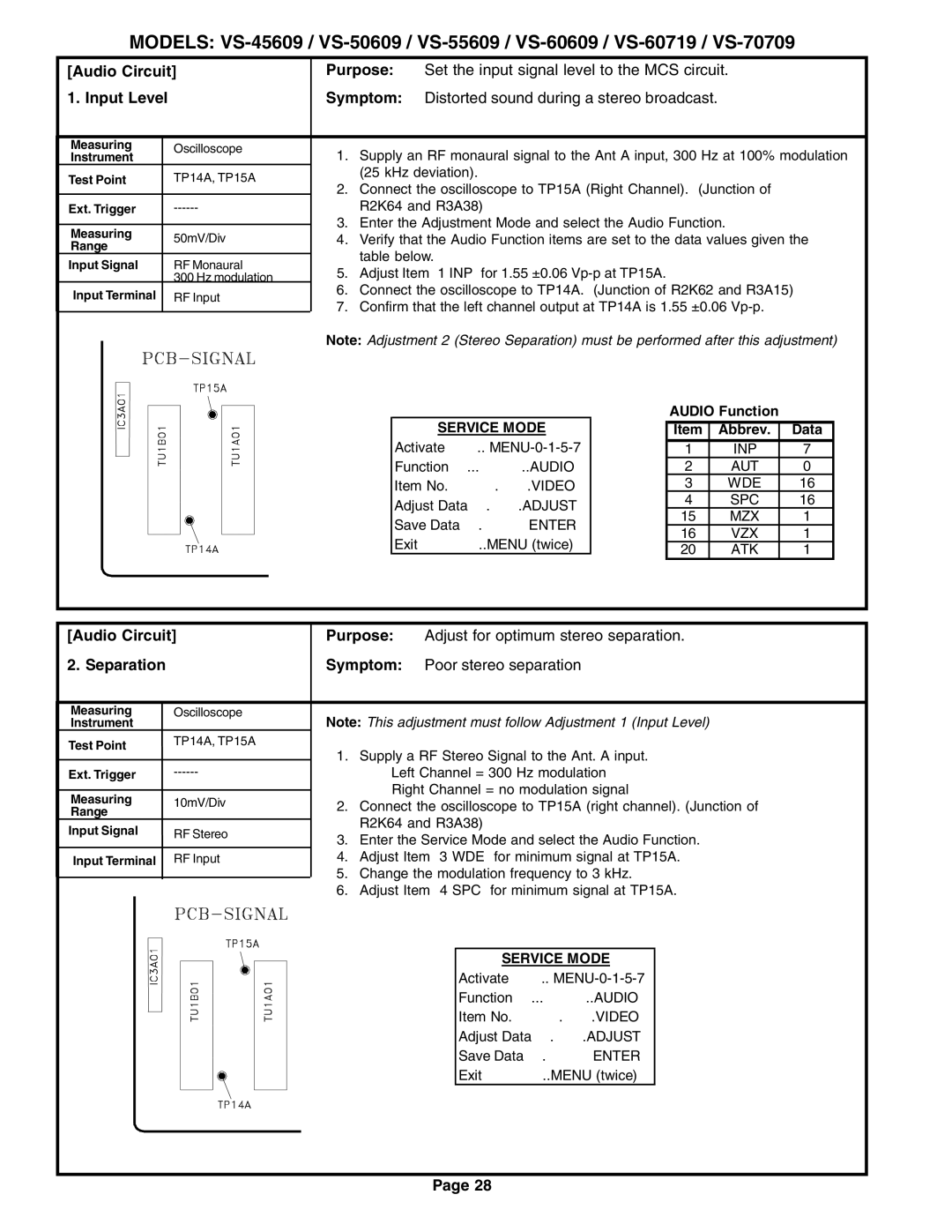
Measuring | Oscilloscope | 1. | Supply an RF monaural signal to the Ant A input, 300 Hz at 100% modulation | |||||
Instrument | ||||||||
| ||||||||
Test Point | TP14A, TP15A |
| (25 kHz deviation). |
|
|
| ||
2. | Connect the oscilloscope to TP15A (Right Channel). (Junction of |
| ||||||
|
|
| ||||||
Ext. Trigger |
| R2K64 and R3A38) |
|
|
| |||
Measuring |
| 3. | Enter the Adjustment Mode and select the Audio Function. |
| ||||
50mV/Div | 4. | Verify that the Audio Function items are set to the data values given the | ||||||
Range | ||||||||
|
| table below. |
|
|
| |||
Input Signal | RF Monaural |
|
|
|
| |||
5. | Adjust Item “1 INP” for 1.55 ±0.06 |
|
|
| ||||
| 300 Hz modulation |
|
|
| ||||
Input Terminal | RF Input | 6. | Connect the oscilloscope to TP14A. (Junction of R2K62 and R3A15) | |||||
7. | Confirm that the left channel output at TP14A is 1.55 ±0.06 |
| ||||||
|
|
| ||||||
|
| Note: Adjustment 2 (Stereo Separation) must be performed after this adjustment) | ||||||
|
|
|
| SERVICE MODE | AUDIO Function |
| ||
|
|
|
| Item | Abbrev. | Data | ||
|
|
|
| Activate …….. | 1 | INP | 7 | |
|
|
|
| Function …...………..AUDIO | 2 | AUT | 0 | |
|
|
|
| Item No. ……….…….VIDEO | 3 | WDE | 16 | |
|
|
|
| Adjust Data ….…….ADJUST | 4 | SPC | 16 | |
|
|
|
| 15 | MZX | 1 | ||
|
|
|
| Save Data …. ………ENTER | ||||
|
|
|
| 16 | VZX | 1 | ||
|
|
|
| Exit …………..MENU (twice) | ||||
|
|
|
| 20 | ATK | 1 | ||
|
|
|
|
| ||||
[Audio Circuit] | Purpose: | Adjust for optimum stereo separation. |
2. Separation | Symptom: | Poor stereo separation |
Measuring | Oscilloscope |
Instrument |
|
Test Point | TP14A, TP15A |
| |
Ext. Trigger | |
Measuring | 10mV/Div |
Range |
|
Input Signal | RF Stereo |
Input Terminal | RF Input |
Note: This adjustment must follow Adjustment 1 (Input Level)
1.Supply a RF Stereo Signal to the Ant. A input.
•Left Channel = 300 Hz modulation
•Right Channel = no modulation signal
2.Connect the oscilloscope to TP15A (right channel). (Junction of R2K64 and R3A38)
3.Enter the Service Mode and select the Audio Function.
4.Adjust Item “3 WDE” for minimum signal at TP15A.
5.Change the modulation frequency to 3 kHz.
6.Adjust Item “4 SPC” for minimum signal at TP15A.
SERVICE MODE
Activate ……..
Function …...………..AUDIO
Item No. ……….…….VIDEO
Adjust Data ….…….ADJUST
Save Data …. ………ENTER
Exit …………..MENU (twice)
Page 28