MODELS:
CABINET SEPARATION PROCEDURE (VS-70709)
Model
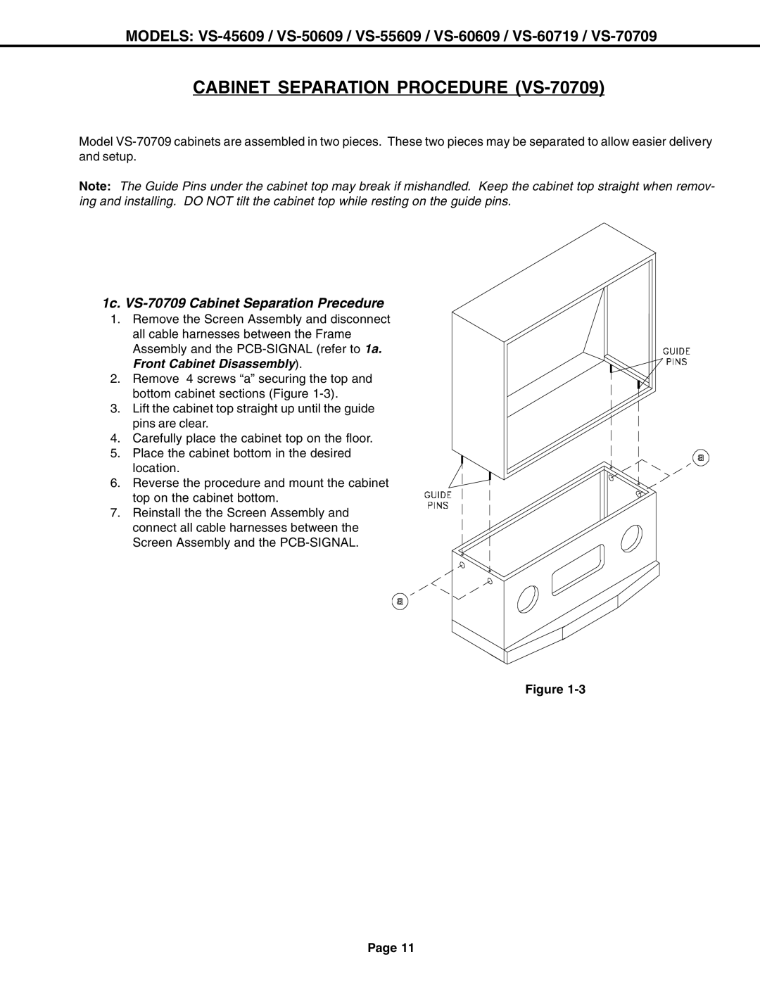
Note: The Guide Pins under the cabinet top may break if mishandled. Keep the cabinet top straight when remov- ing and installing. DO NOT tilt the cabinet top while resting on the guide pins.
1c. VS-70709 Cabinet Separation Precedure
1.Remove the Screen Assembly and disconnect all cable harnesses between the Frame Assembly and the
2.Remove 4 screws “a” securing the top and bottom cabinet sections (Figure
3.Lift the cabinet top straight up until the guide pins are clear.
4.Carefully place the cabinet top on the floor.
5.Place the cabinet bottom in the desired
location.
6.Reverse the procedure and mount the cabinet top on the cabinet bottom.
7.Reinstall the the Screen Assembly and connect all cable harnesses between the Screen Assembly and the
Figure
Page 11