MODELS:
[CRT Circuit] |
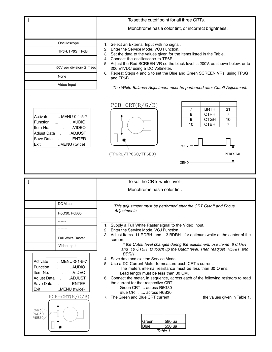
| Purpose: | To set the cutoff point for all three CRTs. |
| ||
7. CRT Cutoff |
| Symptom: | Monchrome has a color tint, or incorrect brightness. | |||
Measuring | Oscilloscope | 1. Select an External Input with no signal. |
|
| ||
Instrument |
|
| ||||
|
|
| ||||
Test Point | TP6R, TP6G, TP6B | 2. Enter the Service Mode, VCJ Function. |
|
| ||
3. Set the data to the values given for the Items listed in the Table. | ||||||
|
| |||||
Ext. Trigger | 4. Connect the oscilloscope to TP6R. |
|
| |||
Measuring | 50V per division/ 2 msec | 5. Adjust the Red SCREEN VR so the black level is 200V, as shown below, or to | ||||
206 ±1VDC using a DC Voltmeter. |
|
| ||||
Range |
| 6. Repeat Steps 4 and 5 to set the Blue and Green SCREEN VRs, using TP6G | ||||
Input Signal | None | |||||
and TP6B. |
|
| ||||
|
|
|
| |||
Input Terminal | Video Input | Note: The White Balance Adjustment must be performed after Cutoff Adjustment. | ||||
|
| |||||
|
|
| VCJ Function |
| ||
|
|
| ITEM | ABBR. | DATA | |
SERVICE MODE |
| 7 | BRTH | 31 | ||
| 8 | CTRH | 7 | |||
Activate …….. |
| |||||
| 9 | CTGH | 10 | |||
Function …...………..AUDIO |
| |||||
| 10 | CTBH | 7 | |||
Item No. ……….…….VIDEO |
| |||||
|
|
|
| |||
Adjust Data ….…….ADJUST |
|
|
|
| ||
Save Data …. ………ENTER |
|
|
|
| ||
Exit …………..MENU (twice) |
|
|
|
| ||
[CRT Circuit] |
|
| Purpose: | To set the CRTs white level | ||
8. White Balance | Symptom: | Monchrome has a color tint. | ||||
| (High Color Temperature) |
|
| |||
|
|
|
|
|
| |
Measuring | DC Meter | Note: This adjustment must be performed after the CRT Cutoff and Focus | ||||
Instrument |
|
| ||||
Test Point | R6G30, R6B30 | Adjustments. | ||||
|
| |||||
|
|
|
| High Color Temperature White Balance | ||
Ext. Trigger |
| |||||
|
|
|
| 1. Supply a Full White Raster signal to the Video Input. | ||
Measuring |
| |||||
| 2. Enter the Service Mode, VCJ Function. | |||||
Range |
|
| ||||
|
| 3. Adjust Items “11 RDRH” and “13 BDRH” for optimum white at the center of the | ||||
Input Signal | Full White Raster | |||||
screen. |
| |||||
|
|
|
|
| ||
Input Terminal | Video Input | Note: If the Cutoff level changes during the adjustment, use Items “8 CTRH” | ||||
and “10 CTBH” to touch up the Cutoff level. Then readjust “RDRH” and | ||||||
|
|
|
| |||
|
|
|
| “BDRH”. | ||
| SERVICE MODE | |||||
| 4. Save data and exit the Service Mode. | |||||
| Activate …….. | |||||
| 5. Use a DC Current Meter to measure each CRT’s current. | |||||
| Function …...………..AUDIO | |||||
| • The meters internal resistance must be less than 30 Ohms. | |||||
| Item No. ……….…….VIDEO | |||||
| • Lead length must be less than 30 CM. | |||||
| Adjust Data ….…….ADJUST | 6. Connect the meter, in sequence, across each of the following resistors to read | ||||
| Save Data …. ………ENTER | the current for that respective CRT. | ||||
| Exit …………..MENU (twice) | • Green CRT ... across R6G30 | ||||
|
|
| ||||
•Blue CRT ...... across R6B30
7. The Green and Blue CRT current must not exceed the values given in Table 1.
Maximun CRT Current
CRT |
| CURRENT |
Green |
| 580 ua |
Blue |
| 530 ua |
| Table 1 | |
Page 31