MODELS:
[Deflection Circuit] | Purpose: | To set the vertical height and linearity. | ||
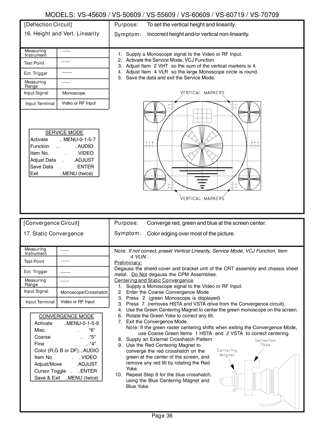
16. Height and Vert. Linearity | Symptom: | Incorrect height and/or vertical | ||
Measuring | 1. | Supply a Monoscope signal to the Video or RF Input. | ||
Instrument |
| |||
Test Point | 2. | Activate the Service Mode, VCJ Function. | ||
| 3. | Adjust Item “2 VHT” so the sum of the vertical markers is 4. | ||
|
| |||
Ext. Trigger | 4. | Adjust Item “4 VLR” so the large Monoscope circle is round. | ||
Measuring | 5. | Save the data and exit the Service Mode. | ||
|
|
| ||
Range |
|
|
|
|
Input Signal | Monoscope |
|
|
|
Input Terminal | Video or RF Input |
|
|
|
SERVICE MODE
Activate ……..
Function …...………..AUDIO
Item No. ……….…….VIDEO
Adjust Data ….…….ADJUST
Save Data …. ………ENTER
Exit …………..MENU (twice)
[Convergence Circuit] | Purpose: | Converge red, green and blue at the screen center. |
17. Static Convergence | Symptom: | Color edging over most of the picture. |
Measuring | |
Instrument |
|
Test Point | |
Ext. Trigger | |
Measuring | |
Range |
|
Input Signal | Monoscope/Crosshatch |
Input Terminal | Video or RF Input |
CONVERGENCE MODE
Activate
Misc. ……………….……"6"
Coarse………………..…."5"
Fine ……………………..."4"
Color (R,G B or DF)...AUDIO Item No………….…..VIDEO
Adjust/Move……….ADJUST
Cursor Toggle….…..ENTER Save & Exit…..MENU (twice)
Note: If not correct, preset Vertical Linearity, Service Mode, VCJ Function, Item “4 VLIN”.
Preliminary:
Degauss the shield cover and bracket unit of the CRT assembly and chassis sheet metal. Do Not degauss the CPM Assemblies.
Centering and Static Convergence
1.Supply a Monoscope signal to the Video or RF Input.
2.Enter the Coarse Convergence Mode
3.Press “2” (green Monoscope is displayed)
3.Press “7” (removes HSTA and VSTA drive from the Convergence circuit).
4.Use the Green Centering Magnet to center the green monoscope on the screen.
6.Rotate the Green Yoke to correct any tilt.
7.Exit the Convergence Mode.
Note: If the green raster centering shifts when exiting the Convergence Mode, use Coarse Green Items “1 HSTA” and “2 VSTA” to correct centering.
8. Supply an External Crosshatch Pattern
9. Use the Red Centering Magnet to converge the red crosshatch on the green at the center of the screen, and remove any red tilt by rotating the Red Yoke.
10.Repeat Step 9 for the blue crosshatch, using the Blue Centering Magnet and Blue Yoke.
Page 36