MODELS:
[Video Circuit] |
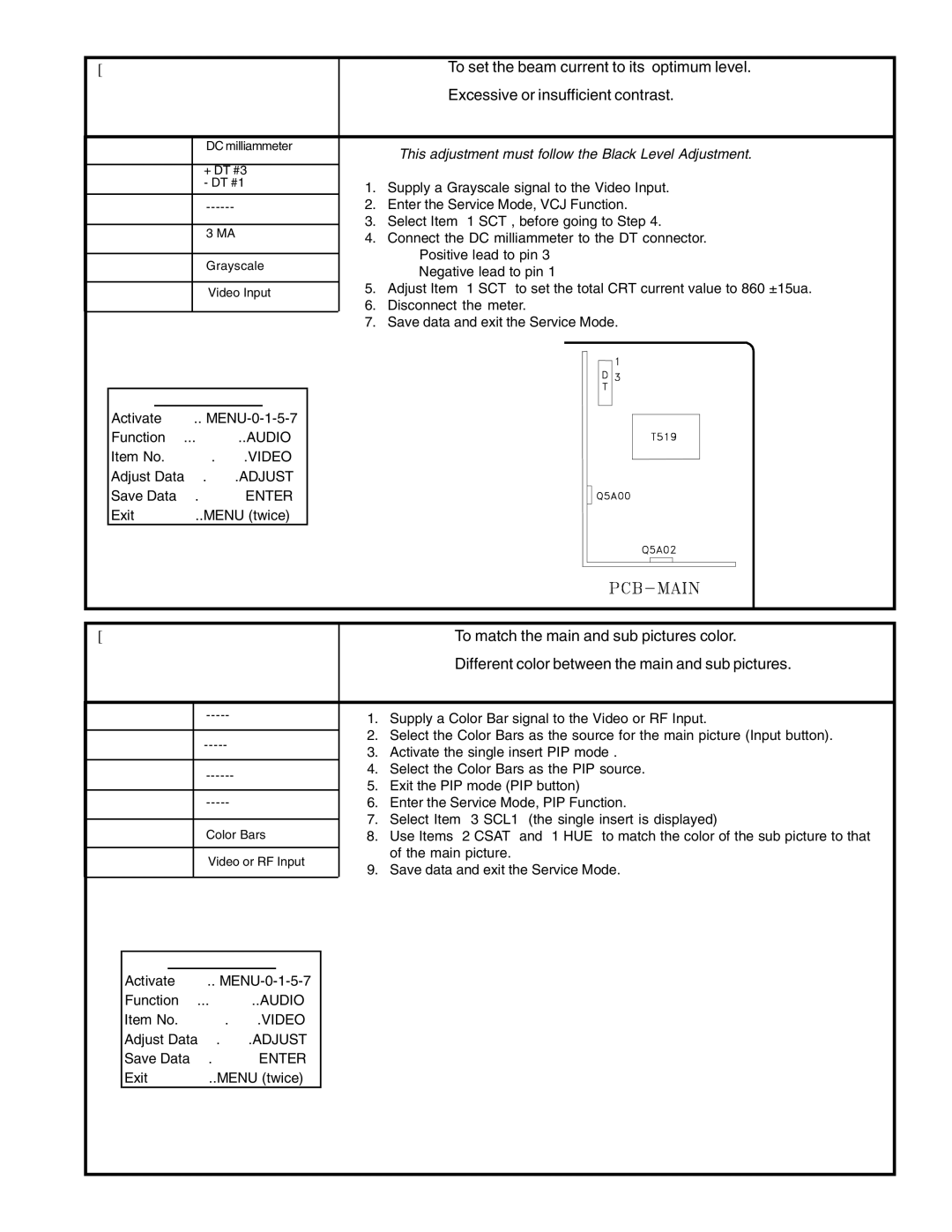
| Purpose: | To set the beam current to its’ optimum level. | ||||
11. Sub Contrast | Symptom: | Excessive or insufficient contrast. | |||||
|
|
|
|
|
|
| |
Measuring |
| DC milliammeter | Note: This adjustment must follow the Black Level Adjustment. | ||||
Instrument |
|
| |||||
Test Point |
| + DT #3 |
|
|
|
|
|
| - DT #1 | 1. | Supply a Grayscale signal to the Video Input. | ||||
|
|
| |||||
Ext. Trigger |
| 2. | Enter the Service Mode, VCJ Function. | ||||
|
|
| 3. | Select Item “1 SCT”, before going to Step 4. | |||
Measuring |
| 3 MA | |||||
| 4. | Connect the DC milliammeter to the DT connector. | |||||
Range |
|
| |||||
|
|
| • Positive lead to pin 3 | ||||
Input Signal |
| Grayscale |
| ||||
|
| • Negative lead to pin 1 | |||||
|
|
|
| ||||
|
|
| 5. | Adjust Item “1 SCT” to set the total CRT current value to 860 ±15ua. | |||
Input Terminal |
| Video Input | |||||
| 6. | Disconnect the meter. | |||||
|
|
| |||||
|
|
| 7. | Save data and exit the Service Mode. | |||
|
|
|
|
|
|
|
|
SERVICE MODE
Activate ……..
Function …...………..AUDIO
Item No. ……….…….VIDEO
Adjust Data ….…….ADJUST
Save Data …. ………ENTER
Exit …………..MENU (twice)
[PIP Circuit] |
| Purpose: | To match the main and sub pictures color. | ||
12. Color and Tint | Symptom: | Different color between the main and sub pictures. | |||
(PIP Insert Picture) |
|
|
| ||
|
|
|
|
| |
Measuring | 1. | Supply a Color Bar signal to the Video or RF Input. | |||
Instrument | |||||
| |||||
Test Point | 2. | Select the Color Bars as the source for the main picture (Input button). | |||
3. | Activate the single insert PIP mode . | ||||
|
| ||||
Ext. Trigger | 4. | Select the Color Bars as the PIP source. | |||
5. | Exit the PIP mode (PIP button) | ||||
|
| ||||
Measuring | 6. | Enter the Service Mode, PIP Function. | |||
Range |
| 7. | Select Item “3 SCL1” (the single insert is displayed) | ||
Input Signal | Color Bars | ||||
8. | Use Items “2 CSAT” and “1 HUE” to match the color of the sub picture to that | ||||
| |||||
|
|
| of the main picture. | ||
Input Terminal | Video or RF Input |
| |||
9. | Save data and exit the Service Mode. | ||||
|
| ||||
SERVICE MODE
Activate ……..
Function …...………..AUDIO
Item No. ……….…….VIDEO
Adjust Data ….…….ADJUST
Save Data …. ………ENTER
Exit …………..MENU (twice)
Page 33