Connecting a DTV Receiver, continued
DTV Receiver with RGB Video Connections
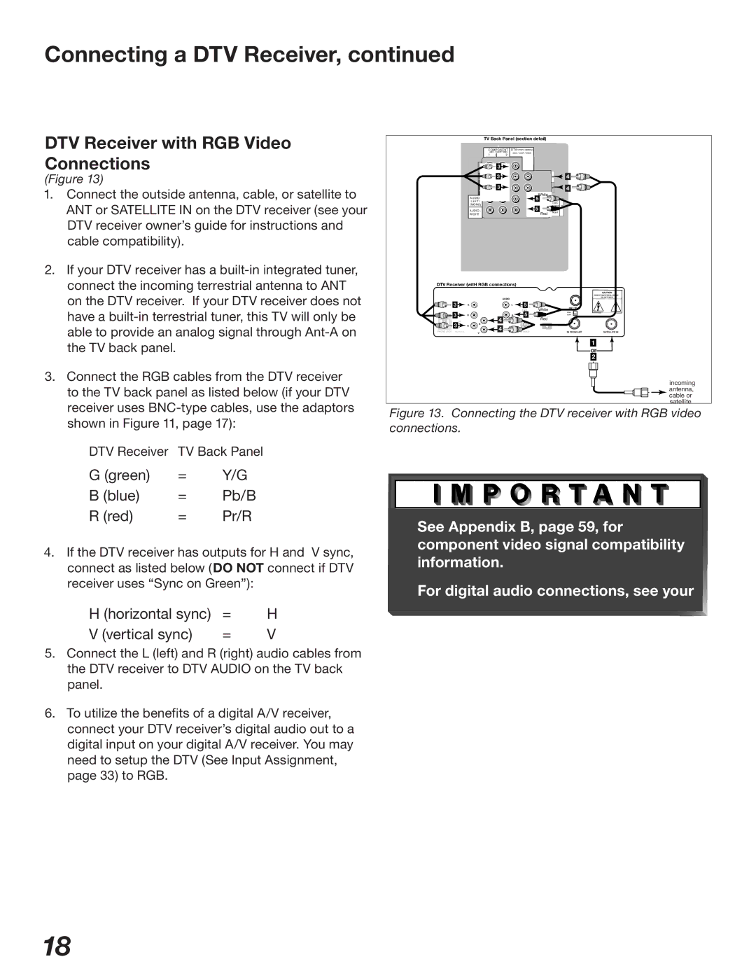
(Figure 13)
1.Connect the outside antenna, cable, or satellite to ANT or SATELLITE IN on the DTV receiver (see your DTV receiver owner’s guide for instructions and cable compatibility).
2.If your DTV receiver has a
3.Connect the RGB cables from the DTV receiver to the TV back panel as listed below (if your DTV receiver uses
DTV Receiver TV Back Panel
TV Back Panel (section detail)
COMPONENT | DTV(YPbPr/ GBRHV ) | |
480 i / 480P/ 1080i | 480i / 480P /1080 i | |
1 | 2 |
|
| 3 |
|
|
P | 3 | H | 4 |
3 |
| V | 4 |
| White |
|
|
AUDIO | 5 | AUDIO- |
|
L E FT |
| ||
|
| LEFT/ |
|
| 5 | (MONO) | DV |
| AUDIO- | I | |
AUDIO - |
| ||
RIGHT | Red | RIGHT |
|
DTV Receiver (witH RGB connections)
|
|
|
|
|
|
|
| CAUTION |
|
|
|
|
|
|
|
| RISK OF ELECTRICAL SHOCK |
|
|
|
| AUDIO |
|
|
| DO NOT OPEN |
| 3 |
|
| 5 |
|
|
| |
|
|
|
|
|
|
| ||
|
| G |
| L | VCR |
|
|
|
|
|
|
|
| CONTROL | White | OUT TO TV |
|
|
|
|
|
| 5 | CH 3 |
| |
| 3 |
|
|
|
|
| ||
| R |
| R | DIGITAL | CH 4 |
| ||
|
|
|
|
| ||||
| RF |
|
| 4 |
| RedAUDIO OUT |
|
|
| 3 | B | H |
|
|
|
|
|
|
|
| 4 |
|
|
|
| |
PHONE JACK | REMOTE |
| V |
| IN FROM ANT | SATELLITE IN | ||
|
|
|
1
or 2
incoming antenna, cable or satellite
Figure 13. Connecting the DTV receiver with RGB video connections.
G (green) | = | Y/G |
B (blue) | = | Pb/B |
R (red) | = | Pr/R |
4.If the DTV receiver has outputs for H and V sync, connect as listed below (DO NOT connect if DTV receiver uses “Sync on Green”):
H (horizontal sync) | = | H |
V (vertical sync) | = | V |
5.Connect the L (left) and R (right) audio cables from the DTV receiver to DTV AUDIO on the TV back panel.
6.To utilize the benefits of a digital A/V receiver, connect your DTV receiver’s digital audio out to a digital input on your digital A/V receiver. You may need to setup the DTV (See Input Assignment, page 33) to RGB.
See Appendix B, page 59, for component video signal compatibility information.
For digital audio connections, see your
18