Specifications (continued)
Specification of RGB signals in each computer mode of the projector (continued)
Important:
•Some computers aren’t compatible with the projector.
•The projector’s maximum resolution is 1920 x
1080 pixels. It may not display images of higher resolutions than 1920 x 1080 correctly.
•Images with SYNC on G (Green) signal may jitter.
•Images with SYNC on G (Green) signal may be tinged with green.
•If the resolution and frequency of your computer aren’t shown on the table, find the compatible resolution and frequency by changing the resolution of your computer.
•TV60 and TV50 are equivalent to 480i and 576i respectively. When these signals are supplied to the VIDEO IN or
•This projector doesn’t support 480p signals from video devices having 4 lines (R, G, B, CS*) or having 5 lines (R, G, B, H, V).
*: Composite Sync
•When a certain signal such as SXGA85, SXGA85b and UXGA60 is input, the number of displayed colors may decrease depending on the setting of ASPECT in the FEATURE menu. Change the signal format of the computer, if necessary.
REAL mode
When moire patterns or lines of uneven thickness appear on the projected image, these symptoms may be improved by displaying it in its original image size (REAL mode). To display the image in the REAL mode, set ASPECT of the FEATURE menu to REAL. (See page 23 for menu setting.)
•In the REAL mode, you cannot change the magnification factor and magnification range.
•Images of which resolution is larger than the panel resolution cannot be displayed in the REAL mode.
•In the REAL mode, images are
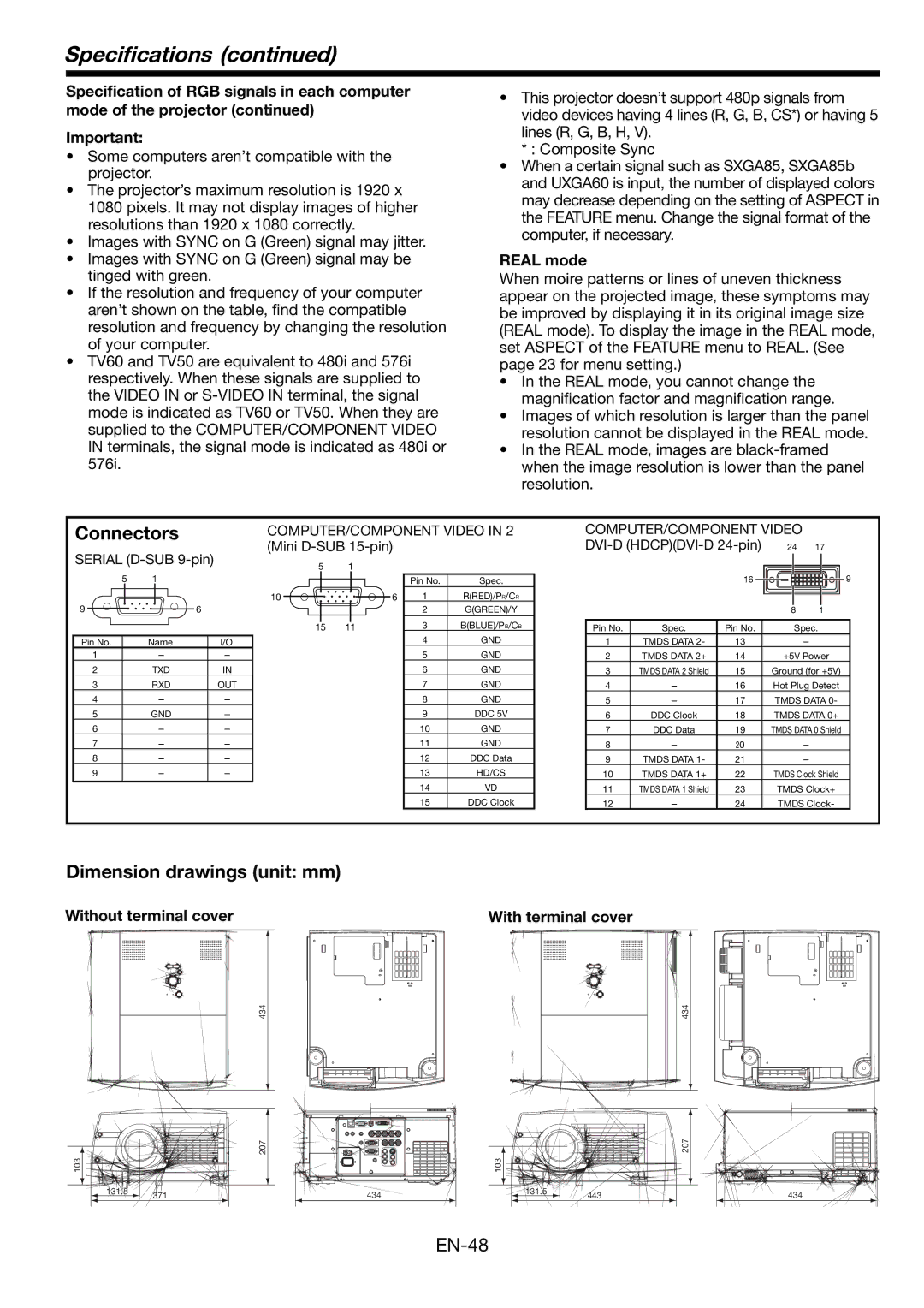
Connectors
COMPUTER/COMPONENT VIDEO IN 2 | COMPUTER/COMPONENT VIDEO |
(Mini |
SERIAL | 5 |
| 1 |
|
|
|
|
|
|
|
|
|
|
|
|
|
|
|
| ||||||||||
5 | 1 |
|
|
|
|
|
|
|
|
|
| Pin No. | Spec. |
|
|
| 16 |
|
|
|
|
|
|
| 9 | ||||
|
|
|
|
|
|
|
|
|
|
|
|
|
|
|
|
|
|
| |||||||||||
9 |
|
|
|
|
| 6 |
| 10 |
|
|
|
|
| 6 | 1 | R(RED)/PR/CR |
|
|
|
|
|
|
|
|
|
|
|
| |
|
|
|
|
|
|
|
|
|
|
|
|
|
|
|
|
|
|
|
|
|
|
| |||||||
|
|
|
|
|
|
|
|
|
|
|
|
|
|
|
|
|
|
|
|
| |||||||||
|
|
|
|
|
|
|
|
|
|
|
|
| 2 | G(GREEN)/Y |
|
|
|
|
| 8 | 1 |
| |||||||
|
|
|
|
|
|
|
|
|
|
|
|
|
|
|
| 3 | B(BLUE)/PB/CB |
|
|
|
|
|
|
|
|
|
|
|
|
|
|
|
|
|
|
|
| 15 | 11 |
|
|
| Pin No. | Spec. | Pin No. |
|
|
| Spec. |
|
|
| |||||||
|
|
|
|
|
|
|
| 4 | GND |
|
|
|
| ||||||||||||||||
Pin No. |
| Name |
| I/O |
|
|
|
|
|
|
|
| 1 | TMDS DATA 2- | 13 |
| - |
|
|
| |||||||||
1 |
| - |
|
| - |
|
|
|
|
|
|
| 5 | GND |
| 2 | TMDS DATA 2+ | 14 |
|
| +5V Power | ||||||||
2 |
|
| TXD |
| IN |
|
|
|
|
|
|
| 6 | GND |
| 3 | TMDS DATA 2 Shield | 15 |
| Ground (for +5V) | |||||||||
3 |
|
| RXD |
| OUT |
|
|
|
|
|
|
| 7 | GND |
| 4 | - | 16 |
| Hot Plug Detect | |||||||||
4 |
| - |
|
| - |
|
|
|
|
|
|
| 8 | GND |
| 5 | - | 17 |
| TMDS DATA 0- | |||||||||
5 |
| GND |
| - |
|
|
|
|
|
|
| 9 | DDC 5V |
| 6 | DDC Clock | 18 |
| TMDS DATA 0+ | ||||||||||
6 |
| - |
|
| - |
|
|
|
|
|
|
| 10 | GND |
| 7 | DDC Data | 19 |
| TMDS DATA 0 Shield | |||||||||
7 |
| - |
|
| - |
|
|
|
|
|
|
| 11 | GND |
| 8 | - | 20 |
| - |
|
|
| ||||||
8 |
| - |
|
| - |
|
|
|
|
|
|
| 12 | DDC Data |
| 9 | TMDS DATA 1- | 21 |
| - |
|
|
| ||||||
9 |
| - |
|
| - |
|
|
|
|
|
|
| 13 | HD/CS |
| 10 | TMDS DATA 1+ | 22 |
| TMDS Clock Shield | |||||||||
|
|
|
|
|
|
|
|
|
|
|
|
|
|
|
| 14 | VD |
| 11 | TMDS DATA 1 Shield | 23 |
| TMDS Clock+ | ||||||
|
|
|
|
|
|
|
|
|
|
|
|
|
|
|
|
|
| ||||||||||||
|
|
|
|
|
|
|
|
|
|
|
|
|
|
|
| 15 | DDC Clock |
| 12 | - | 24 |
| TMDS Clock- | ||||||
Dimension drawings (unit: mm)
Without terminal cover | With terminal cover | ||
|
|
|
|
434
434
103 |
|
131.5 | 371 |
|
207
434 |
| 207 |
103 |
|
131.5 | 443 |
|
434 |