Consumer Retain this manual for future refer- ence
Cdvt
Cdvr
Do not try to light any appliance
Operating Instructions Electronic Ignition
Pre-Installation Information
Electrical Wiring
Check Gas Pressure Signature Command System36
Installer
Important Safety Information
Owner
As wellhead gas
Code Approval
Never connect unit to private non-utility
Gas wells. This gas is commonly known
Product Specifications
Product features
GAS pressures
GAS Specifications & Orifice Size Cdvr Series
GAS Specifications & Orifice Size Cdvt Series
High Elevations
Framing Dimensions
Fireplace dimensions & Framing
CDVR33V,E7
CDVT36 V,E,SC7 CDVT42 V,E,SC7 CDVT47 V,E,SC7
CDVT33V,E,SC7
Cold Climate Insulation
Fireplace Location
Clearances to combustibles
Clearances
Mantel clearances
Finishing Material
Installation precautions
Venting Installation Information
General Venting
General Venting Information Termination Location
Canadian Installations1 US Installations2
Canadian Installations
USA Installations
Termination Clearances
Twist Lock Pipes
Rear Vent Installation only
Refer to Page 24 for snorkel requirements
How to Use the Vent Graph
Vent Pipe Clearances
Venting installation
Rear Wall Vent Application
Rear Wall Vent Installation Twist Lock Pipe
Step
Venting System
Rear Wall Vent Installations Flex Vent Pipe
Top vent Sidewall Application
Since it is very im Portant That
Maximum number of 90 elbows per side wall
Always install horizontal venting on a level plane
Vertical Sidewall Installation Twist Lock Pipe
Vertical Sidewall installation flex vent pipe
Vertical THROUGH-THE-ROOF APPLICA- Tion
Below Grade Installation
Do not back fill around snorkel
Vertical THROUGH-THE-ROOF Installation
Minimum Chimney Clearance
Install gas piping to fireplace / burner system location
Fireplace installation
Check gas type
Natural Gas
Do not use open flame to check for gas
Electrical Wiring
Leaks
Remote Wall Switch
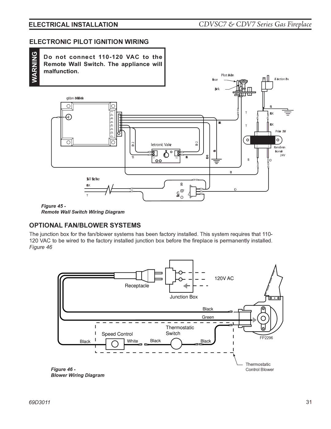
Electrical installation
Remote Wall mounted Switch
Do not connect wall switch to 110
Do not connect 110-120 VAC to
Electronic Pilot Ignition Wiring
Remote Wall Switch. The appliance will
Optional Fan/Blower Systems
Never use an open flame to check for gas leak
Leak testing
Millivolt Operating Instructions
Initial lighting
Never check for gas leak with open flame
Approved leak testing method
Lighting the burner
Main burner switch
Pilot position
Injury or loss of life
Causing property damage, personal
If you do not follow these instruction
Exactly, a fire or explosion may result
Or performing service. All wiring shall be
Optional Accessory Requirements
Electrician. Main power must be off when
Connecting to main electrical power supply
Wall Switch Installation
Electrical Installation
Junction BOX Wiring
Command Center Wall Installation
Electrical Installation
Optional FAN Blower Systems
Blotsc Signature Command Blower
FK-12 Manual Blower
Blot Automatic Thermostat Blower
On next
OPERATing Instructions
Command Center
Battery Installation
Features
Command Center
Key Combinations for System Settings
System CONFIGURATION/SETUP
Function Operation Default Setting
Function Operation
Command Center Operations
Self Diagnostics Chart
FUNCTIONS/OPERATION
Glass Frame Removal
Rock wool placement
Lava rock and ember placement
Log placement
Burner, Pilot and Control Compart- ment
Cleaning and maintenance
Rock wool
Vent System
Glass Door
Logs
Standing Pilot Ignition
Troubleshooting
PoSSIBLE Cause
CDVSC7 & CDV7 Series Gas Fireplace
YeS
Electronic Ignition
Operationfault Diagnosis Action
Signature Command System
Firebox components
Replacement parts
CDVR33 CDVT33 CDVR36 CDVT36 CDVR42 CDVT42 CDVR47 CDVT47
Standing Pilot Millivolt control
LP to Natural Gas
Replacement Parts
Accessories Description Qty Part Number
Fuel Conversion Kits Millivolt Natural Gas to LP
Electronic Ignition
CDVSC7 & CDV7 Series Gas Fireplace
13,14,15,16,17
CDVR33NSC7
CDVR33SC7
Description Model Number
Vertical Venting
7TBRHTK
Horizontal Venting
CDVSC7 & CDV7 Series Gas Fireplace
CDVSC7 & CDV7 Series Gas Fireplace
Carbon Monoxide Detector Requirements
If Warranty Service is Needed
Lifetime Warranty
Five Year Warranty
Basic Warranty
Model EnerGuide Ratings Fireplace Efficiency %
Mhsc