venting installation
INSTALLATION FOR HORIZONTAL TERMI- NATION
1. Determine the route your horizontal venting will take.
Note: The location of the horizontal vent termination on the exterior wall must meet all local and national building codes.
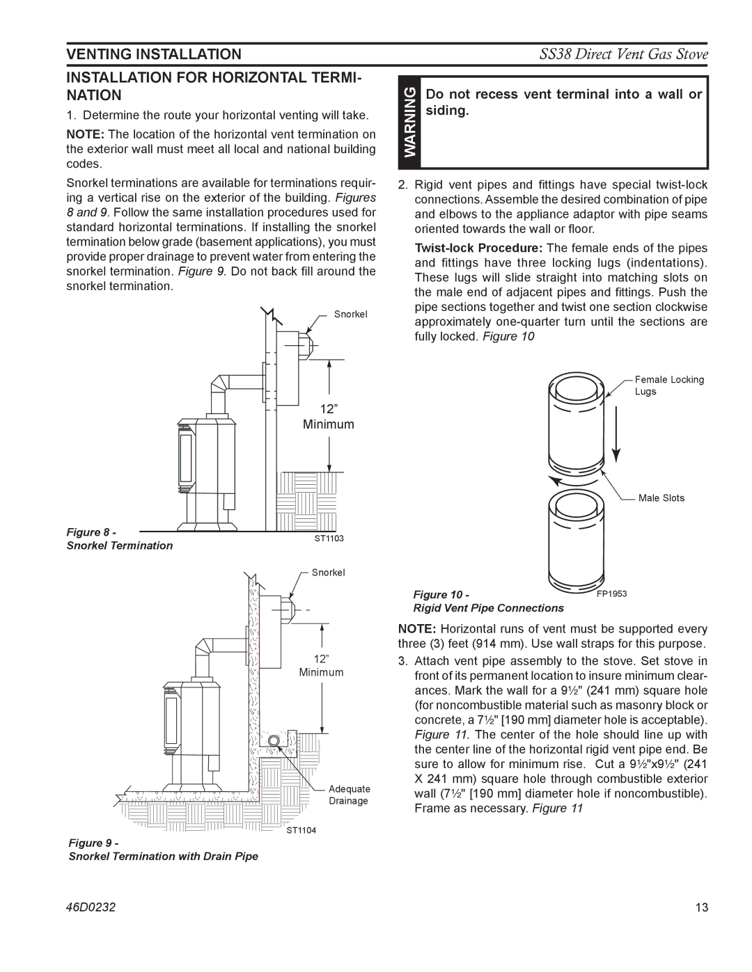
Snorkel terminations are available for terminations requir- ing a vertical rise on the exterior of the building. Figures 8 and 9. Follow the same installation procedures used for standard horizontal terminations. If installing the snorkel termination below grade (basement applications), you must provide proper drainage to prevent water from entering the snorkel termination. Figure 9. Do not back fill around the snorkel termination.
| Snorkel | |
| 12” | |
| Minimum | |
Figure 8 - | ST1103 | |
Snorkel Termination | ||
|
Snorkel
12”
Minimum
Adequate
Drainage
ST1104
Figure 9 -
Snorkel Termination with Drain Pipe
SS38 Direct Vent Gas Stove
| WARNING | Do not recess vent terminal into a wall or |
| siding. | |
|
| |
|
|
|
2.Rigid vent pipes and fittings have special
Female Locking
Lugs
![]()
![]() Male Slots
Male Slots
Figure 10 - | FP1953 |
Rigid Vent Pipe Connections |
|
Note: Horizontal runs of vent must be supported every three (3) feet (914 mm). Use wall straps for this purpose.
3.Attach vent pipe assembly to the stove. Set stove in front of its permanent location to insure minimum clear- ances. Mark the wall for a 9Z\x" (241 mm) square hole (for noncombustible material such as masonry block or concrete, a 7Z\x" [190 mm] diameter hole is acceptable). Figure 11. The center of the hole should line up with the center line of the horizontal rigid vent pipe end. Be sure to allow for minimum rise. Cut a 9Z\x"x9Z\x" (241 X 241 mm) square hole through combustible exterior wall (7Z\x" [190 mm] diameter hole if noncombustible).
Frame as necessary. Figure 11
46D0232 | 13 |