SS38 Direct Vent Gas Stove | VENTING INSTALLATION |
H1
V1
|
| HOT |
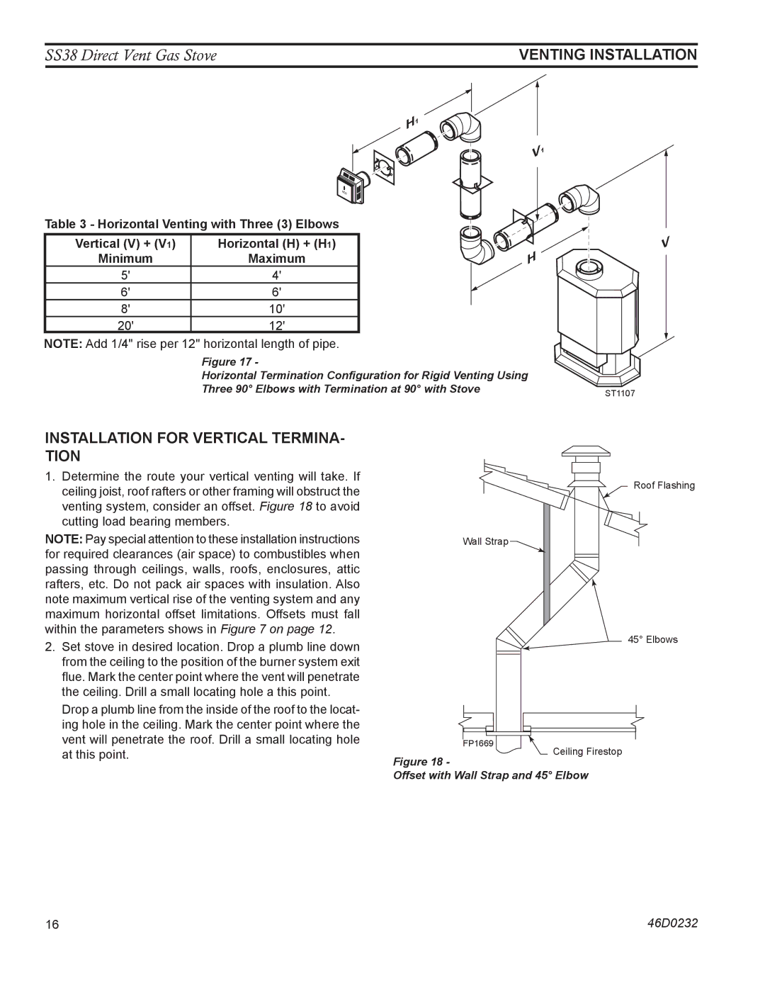
Table 3 - Horizontal Venting with Three (3) Elbows |
| |
Vertical (V) + (V1) | Horizontal (H) + (H1) |
|
Minimum | Maximum | H |
5' | 4' |
|
6' | 6' |
|
8' | 10' |
|
20' | 12' |
|
NOTE: Add 1/4" rise per 12" horizontal length of pipe.
Figure 17 -
Horizontal Termination Configuration for Rigid Venting Using
Three 90° Elbows with Termination at 90° with Stove
V
ST1107
INSTALLATION FOR VERTICAL TERMINA- TION
1.Determine the route your vertical venting will take. If ceiling joist, roof rafters or other framing will obstruct the venting system, consider an offset. Figure 18 to avoid cutting load bearing members.
NOTE: Pay special attention to these installation instructions for required clearances (air space) to combustibles when passing through ceilings, walls, roofs, enclosures, attic rafters, etc. Do not pack air spaces with insulation. Also note maximum vertical rise of the venting system and any maximum horizontal offset limitations. Offsets must fall within the parameters shows in Figure 7 on page 12.
Roof Flashing
Wall Strap![]()
2.Set stove in desired location. Drop a plumb line down from the ceiling to the position of the burner system exit flue. Mark the center point where the vent will penetrate the ceiling. Drill a small locating hole a this point.
Drop a plumb line from the inside of the roof to the locat- ing hole in the ceiling. Mark the center point where the vent will penetrate the roof. Drill a small locating hole at this point.
FP1669
Figure 18 -
45° Elbows
Ceiling Firestop
Offset with Wall Strap and 45° Elbow
16 | 46D0232 |