VENTING INSTALLATION
FLAT CEILING INSTALLATION
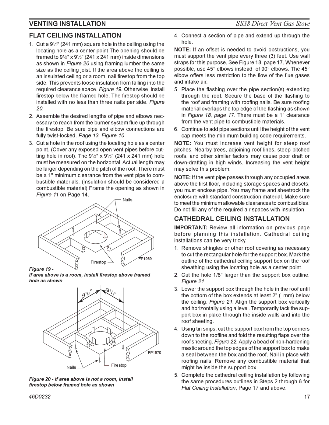
1.Cut a 9Z\x" (241 mm) square hole in the ceiling using the locating hole as a center point The opening should be framed to 9Z\x" x 9Z\x" (241 x 241 mm) inside dimensions as shown in Figure 20 using framing lumber the same size as the ceiling joist. If the area above the ceiling is an insulated ceiling or a room, nail firestop from the top side. This prevents loose insulation from falling into the required clearance space. Figure 19. Otherwise, install firestop below the framed hole. The firestop should be installed with no less than three nails per side. Figure 20.
2.Assemble the desired lengths of pipe and elbows nec- essary to reach from the burner system flue up through the firestop. Be sure pipe and elbow connections are fully
3.Cut a hole in the roof using the locating hole as a center point. (Cover any exposed open vent pipes before cut- ting hole in roof). The 9Z\x" x 9Z\x" (241 x 241 mm) hole must be measured on the horizontal. Actual length may be larger depending on the pitch of the roof. There must be a 1" minimum clearance from the vent pipe to com- bustible materials. (Insulation should be considered a combustible material) Frame the opening as shown in Figure 11 on Page 14.
Nails
SS38 Direct Vent Gas Stove
4.Connect a section of pipe and extend up through the hole.
NOTE: If an offset is needed to avoid obstructions, you must support the vent pipe every three (3) feet. Use wall straps for this purpose. See Figure 18, page 17. Whenever possible, use 45° elbows instead of 90° elbows. The 45° elbow offers less restriction to the flow of the flue gases and intake air.
5.Place the flashing over the pipe section(s) extending through the roof. Secure the base of the flashing to the roof and framing with roofing nails. Be sure roofing material overlaps the top edge of the flashing as shown in Figure 18, page 17. There must be a 1" clearance from the vent pipe to combustible materials.
6.Continue to add pipe sections until the height of the vent cap meets the minimum building code requirements.
NOTE: You must increase vent height for steep roof pitches. Nearby trees, adjoining roof lines, steep pitched roofs, and other similar factors may cause poor draft or
NOTE: If the vent pipe passes through any occupied areas above the first floor, including storage spaces and closets, you must enclose pipe. You may frame and sheetrock the enclosure with standard construction material. Make sure to meet the minimum allowable clearances to combustibles. Do not fill any of the required air spaces with insulation.
CATHEDRAL CEILING INSTALLATION
IMPORTANT: Review all information on previous page before planning this installation. Cathedral ceiling installations can be very tricky.
Firestop
Figure 19 -
FP1969
1. Remove shingles or other roof covering as necessary |
to cut the rectangular hole for the support box. Mark the |
outline of the cathedral ceiling support box on the roof |
sheathing using the locating hole as a center point. |
If area above is a room, install firestop above framed hole as shown
|
|
|
|
| 9 |
|
|
|
|
| " | 1 |
|
|
| / |
| / | ||
|
|
|
|
| 2 | |
9 | 1 |
| 2 |
|
| " |
|
|
|
| |||
|
|
|
|
|
| |
|
|
|
|
|
|
|
FP1970
NailsFirestop
Figure 20 - If area above is not a room, install firestop below framed hole as shown
2. | Cut the hole 1/8" larger than the support box outline. |
| Figure 21 |
3. | Lower the support box through the hole in the roof until |
| the bottom of the box extends at least 2" ( mm) below |
| the ceiling. Figure 21. Align the support box vertically |
| and horizontally using a level. Temporarily tack the sup- |
| port box in place through the inside walls and into the |
| roof sheeting. |
4. | Using tin snips, cut the support box from the top corners |
| down to the roofline and fold the resulting flaps over the |
| roof sheeting. Figure 22. Apply a bead of |
| mastic around the top edges of the support box to make |
| a seal between the box and the roof. Nail in place with |
| roofing nails. Remove any combustible material that |
| might be inside the support box. |
5. | Complete the cathedral ceiling installation by following |
| the same procedures outlines in Steps 2 through 6 for |
| Flat Ceiling Installation, Page 17 and above. |
46D0232 | 17 |