4 DIAGNOSTICS
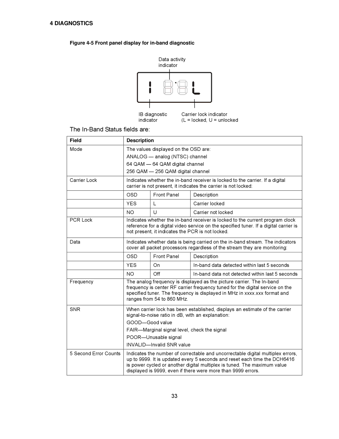
Figure 4-5 Front panel display for in-band diagnostic
Data activity indicator
|
| IB diagnostic | Carrier lock indicator | ||
|
| indicator | (L = locked, U = unlocked | ||
The |
|
| |||
|
|
|
|
| |
Field | Description |
|
| ||
|
|
|
| ||
Mode | The values displayed on the OSD are: | ||||
| ANALOG — analog (NTSC) channel | ||||
| 64 QAM — 64 QAM digital channel | ||||
| 256 QAM — 256 QAM digital channel | ||||
|
|
|
| ||
Carrier Lock | Indicates whether the | ||||
| carrier is not present, it indicates the carrier is not locked: | ||||
|
|
|
|
|
|
| OSD |
| Front Panel |
| Description |
|
|
|
|
|
|
| YES |
| L |
| Carrier locked |
|
|
|
|
|
|
| NO |
| U |
| Carrier not locked |
|
|
|
| ||
PCR Lock | Indicates | whether the | receiver is locked to the current program clock | ||
| reference for a digital video service on the specified tuner. If a digital carrier is | ||||
| not present, it indicates the PCR is not locked. | ||||
|
| ||||
Data | Indicates whether data is being carried on the | ||||
| cover all packet processors regardless of the stream they are monitoring: | ||||
| OSD |
| Front Panel |
| Description |
|
|
|
|
|
|
| YES |
| On |
| |
|
|
|
|
|
|
| NO |
| Off |
| |
|
|
|
| ||
Frequency | The analog | frequency is displayed as the picture carrier. The | |||
| frequency is center RF carrier frequency tuned for the digital service on the | ||||
| specified tuner. The frequency is displayed in MHz in xxxx.xxx format and | ||||
| ranges from 54 to 860 MHz. | ||||
|
| ||||
SNR | When carrier lock has been established, displays an estimate of the carrier | ||||
| |||||
|
|
| |||
| |||||
| |||||
| |||||
|
| ||||
5 Second Error Counts | Indicates the number of correctable and uncorrectable digital multiplex errors, | ||||
| up to 9999. It is updated every 5 seconds and reset each time the DCH6416 | ||||
| is power cycled or another digital multiplex is tuned. The maximum value | ||||
| displayed is 9999, even if there were more than 9999 errors. | ||||
33
