Level 1 and 2 Service Manual | Disassembly |
Removing and Replacing the Display Assembly
GUse only
To remove the Display Assembly
1.Follow the procedures to remove the:
•Battery Door
•Battery
•SIM card
•Front Housing
•Rear Housing
•Joystick Assembly
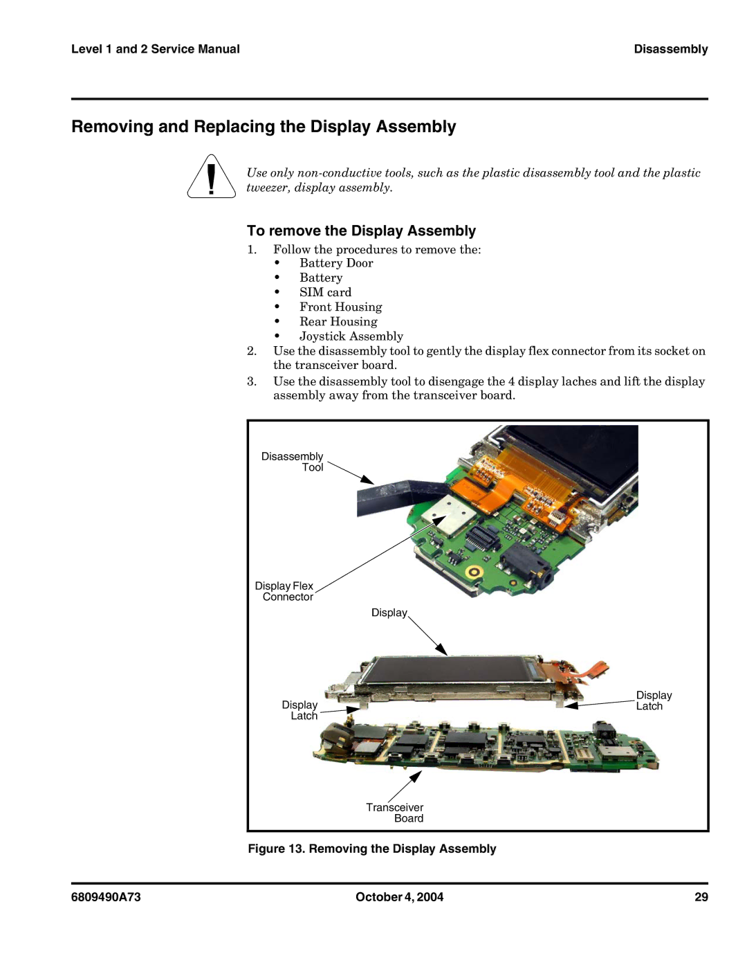
2.Use the disassembly tool to gently the display flex connector from its socket on the transceiver board.
3.Use the disassembly tool to disengage the 4 display laches and lift the display assembly away from the transceiver board.
Disassembly
Tool ![]()
Display Flex
Connector
Display
Display
Display![]() Latch
Latch
Latch
Transceiver
Board
Figure 13. Removing the Display Assembly
6809490A73 | October 4, 2004 | 29 |