NPort 5110 Series User’s Manual | Getting Started |
Panel Layout
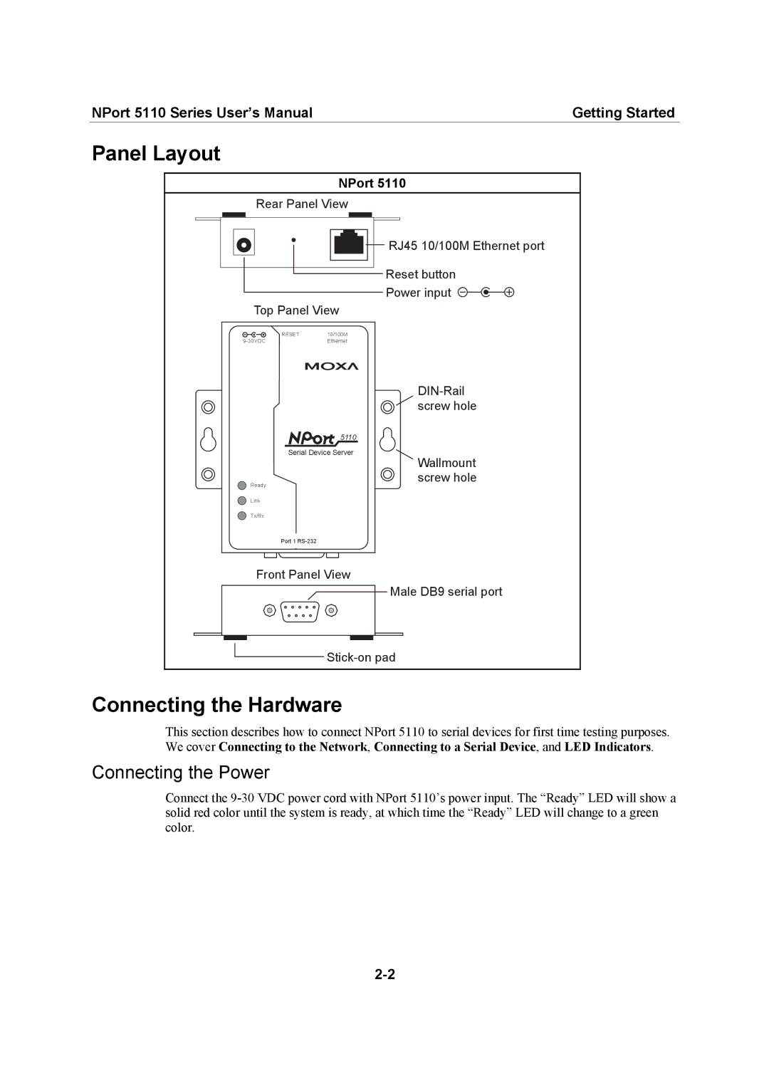
NPort 5110
Rear Panel View
RJ45 10/100M Ethernet port
Reset button
Power input ![]()
Top Panel View
RESET | 10/100M |
Ethernet | |
| 5110 |
Serial Device Server | |
Ready |
|
Link |
|
Tx/Rx |
|
Port 1 |
|
Wallmount screw hole
Front Panel View
Male DB9 serial port |
Connecting the Hardware
This section describes how to connect NPort 5110 to serial devices for first time testing purposes. We cover Connecting to the Network, Connecting to a Serial Device, and LED Indicators.
Connecting the Power
Connect the