Introduction
Rear Panel
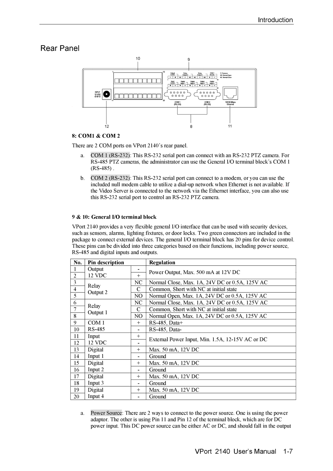
8: COM1 & COM 2
There are 2 COM ports on VPort 2140’s rear panel.
a.COM 1
b.COM 2
9 & 10: General I/O terminal block
VPort 2140 provides a very flexible general I/O interface that can be used with security devices, such as sensors, alarms, lighting fixtures, or door locks. Two green connectors are included in the package to connect external devices. The general I/O terminal block has 20 pins for device control. These pins can be divided into three categories based on their functions, including power source,
No. | Pin description |
| Regulation | |
1 | Output | - | Power Output, Max. 500 mA at 12V DC | |
2 | 12 VDC | + | ||
| ||||
3 | Relay | NC | Normal Close, Max. 1A, 24V DC or 0.5A, 125V AC | |
4 | C | Common, Short with NC at initial state | ||
Output 2 | ||||
5 | NO | Normal Open, Max. 1A, 24V DC or 0.5A, 125V AC | ||
| ||||
6 | Relay | NC | Normal Close, Max. 1A, 24V DC or 0.5A, 125V AC | |
7 | C | Common, Short with NC at initial state | ||
Output 1 | ||||
8 | NO | Normal Open, Max. 1A, 24V DC or 0.5A, 125V AC | ||
| ||||
9 | COM 1 | + | ||
10 | - | |||
11 | Input | + | External Power Input, Min. 1.5A, | |
12 | 12 VDC | - | ||
| ||||
13 | Digital | + | Max. 50 mA, 12V DC | |
14 | Input 1 | - | Ground | |
15 | Digital | + | Max. 50 mA, 12V DC | |
16 | Input 2 | - | Ground | |
17 | Digital | + | Max. 50 mA, 12V DC | |
18 | Input 3 | - | Ground | |
19 | Digital | + | Max. 50 mA, 12V DC | |
20 | Input 4 | - | Ground |
a.Power Source: There are 2 ways to connect to the power source. One is using the power adaptor. The other is using Pin 11 and Pin 12 of the terminal block, which are for DC power input. This DC power source can be either AC or DC, and should fall in the output
VPort 2140 User’s Manual