range between 12V and 15V. Polarity does not matter if you use AC. The DC output through Pin 1 and Pin 2 is fed from the power adaptor of the Video Server or pin 11 and pin 12 if an external power source is attached. The current of external devices is limited to less than 500 mA.
b.COM 1
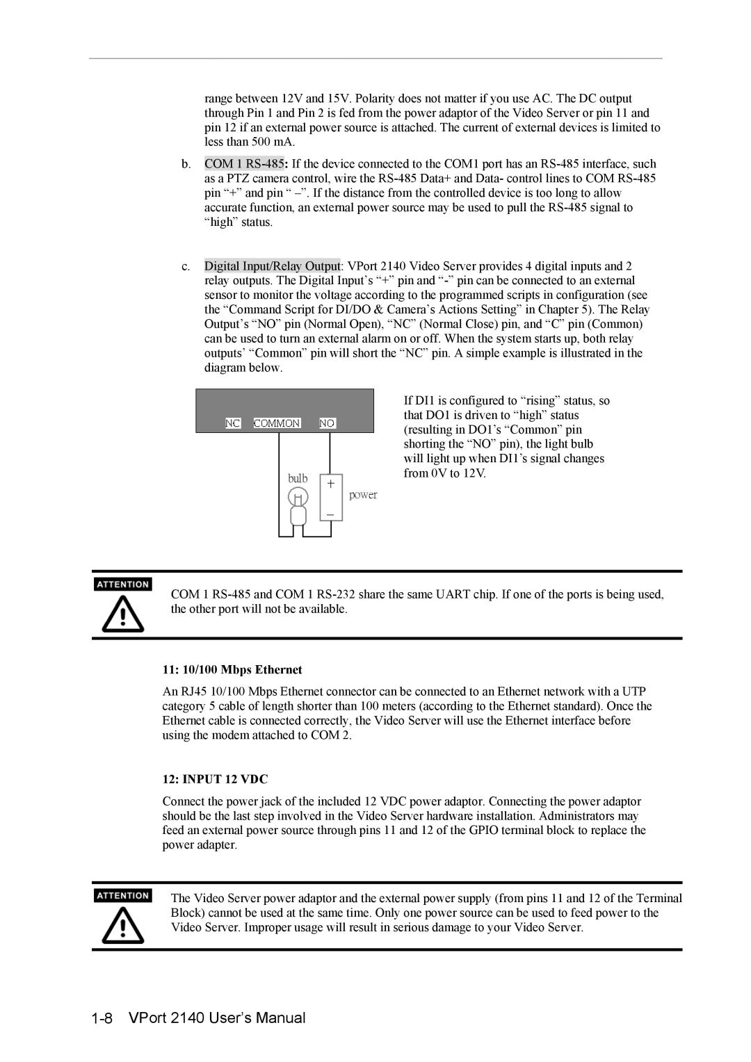
c.Digital Input/Relay Output: VPort 2140 Video Server provides 4 digital inputs and 2 relay outputs. The Digital Input’s “+” pin and
If DI1 is configured to “rising” status, so that DO1 is driven to “high” status (resulting in DO1’s “Common” pin shorting the “NO” pin), the light bulb will light up when DI1’s signal changes from 0V to 12V.
COM 1
11: 10/100 Mbps Ethernet
An RJ45 10/100 Mbps Ethernet connector can be connected to an Ethernet network with a UTP category 5 cable of length shorter than 100 meters (according to the Ethernet standard). Once the Ethernet cable is connected correctly, the Video Server will use the Ethernet interface before using the modem attached to COM 2.
12: INPUT 12 VDC
Connect the power jack of the included 12 VDC power adaptor. Connecting the power adaptor should be the last step involved in the Video Server hardware installation. Administrators may feed an external power source through pins 11 and 12 of the GPIO terminal block to replace the power adapter.
The Video Server power adaptor and the external power supply (from pins 11 and 12 of the Terminal Block) cannot be used at the same time. Only one power source can be used to feed power to the Video Server. Improper usage will result in serious damage to your Video Server.