MQ Power DCA-60SSI2 Whisperwatttm Generator
Page
Heres HOW to GET Help
Table of Contents
Parts Ordering Procedures
Earn Extra Discounts when You order by FAX
Rules for Safe Operation
General Safety
Radiator
Rules for Safe Operation
Loading and Unloading Crane
Battery
Emergencies
Maintenance Safety
Transporting
DCA-60SSI2 -TOWING Rules for Safe Operation
Towing Safety Precautions
Explanation of Chart
DCA-60SSIU -TRAILER-SAFETY Guidelines
TRLR-100XF
DCA-60SSIU -TRAILER-SPECIFICATIONS
Electrical
DCA-60SSIU -TRAILER-SPECIFICATIONS
Electric Brakes
DCA-60SSIU -TRAILER Safety Guidelines
Electric Brake Adjustment
Brakes
Hydraulic/Air/Surge Brakes
DCA-60SSIU -TRAILER Safety Guidelines
Suspension
Tires/Wheels/Lug Nuts
Tire Wear/Inflation
Lug Nut Torque Requirements
Torque Ft.-Lbs
DCA-60SSIU -TRAILER-WIRING Diagram
Electric Brake Troubleshooting
DCA-60SSIU -TRAILER-BRAKETROUBLESHOOTING
Hydraulic Brake Troubleshooting
DCA-60SSIU -TRAILER-BRAKETROUBLESHOOTING
DCA-60SSI2 Generator Decals
DCA-60SSI2 Generator Decals
Generator Specifications
DCA-60SSI2 Specifications
DCA-60SSI2 General Information
Major Components
DCA-60SSI2 Major Components
Dimensions
DCA-60SSI2 Dimensions TOP, Side and Front
Page
Control Panel
DCA-60SSI2 Control Panel
DCA-60SSI2 Control Panel
Engine Operating Panel
DCA-60SSI2 Engine Operating Panel
DCA-60SSI2 Engine Operating Panel
Generator Grounding
Connecting Load
DCA-60SSIU Outputterminal Panel
Volt Receptacle
Output Panel Location
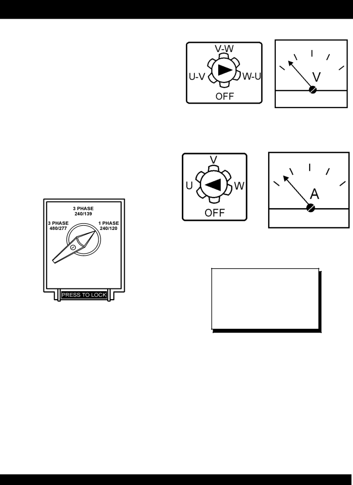
DCA-60SSIU Outputterminal Voltage Selection
DCA-60SSIU Output Amperage Setup
Receptacle Use
DCA-60SSIU Output Amperage Setup
How To Read The Output Terminal Gauges
240/120V Hard Wire Hookup
DCA-60SSIU Output Voltage Setup
Single Phase 277V, 254V, or
DCA-60SSIU Output Voltage Setup
Single Phase 480V, 440V, or 416 Volt
Phase, 480V, 440V, or 416 Volt
Single Phase 139V, 127V, or
DCA-60SSIU Output Voltage Setup
Single Phase 240V, 220V, or 208 Volt
Phase, 240V, 220V, or 208 Volt
Single Phase, 240 Volt
Voltage Selector Switch- Single Phase 240/120V Position
Single Phase 120 Volt
Mounting
DCA-60SSI2 Installation
Outdoor Installation
Typical Generator Grounding Application
DCA-60SSI2 Installation
DCA-60SSI2 PRE-SETUP
Coolant
Lubrication Oil
Adjusting Fan Belt
DCA-60SSIU PRE-SETUP
Cleaning the Outer Radiator
Air Cleaner Fan Belt Tension
Alternator
DCA-60SSIU PRE-SETUP
Battery Cable Installation
Wiring
DCA-60SSI2 Load Application
Single Phase Load
Three Phase Load
Before Starting Generator and Control Panel
DCA-60SSI2 Generator START-UP Procedure
Before Starting Engine
Is pushed
DCA-60SSI2 Generator START-UP Procedure
Abnormal condition occurs
Engine Shutdown
DCA-60SSI2 Generator SHUT-DOWN Procedure
Page
DCA-60SSIU Maintenance
Flushing Out Radiator and Replacing Coolant
DCA-60SSIU Maintenance
Feed Pump Strainer Cleaning
Valve Clearance Check
Injection Timing Check and Adjustment
Generator Storage
Inspection / Maintenance
DCA-60SSI2 Generator Wiring Diagram
DCA-60SSI2 Enginewiring Diagram
Engine Troubleshooting
DCA-60SSI2 -TROUBLESHOOTING Engine
DCA-60SSI2 -TROUBLESHOOTING Engine
Generator Troubleshooting
DCA-60SSI2 -TROUBLESHOOTING GENERATOR/ENGINE
Page
Items Found In the Items Number Column
Explanation of Code in Remarks Column
Qty Description
DCA-60SSI2 Suggested Spare Parts
DCA-60SSI2 --- Generator Assy
DCA-60SSI2
DCA-60SSI2 --- Generator Assy
COVER, END Bracket
DCA-60SSI2 --- Control BOX Assy
Control BOX Assy
DCA-60SSI2 --- Control BOX Assy
Cover
DCA-60SSI2 Engine and Radiator Assy
Hose Band
DCA-60SSI2 Engine and Radiator Assy
Drian Joint
DCA-60SSI2 --- Engine Operating Panel Assy
DCA-60SSI2
DCA-60SSI2 --- Engine Operating Panel Assy
Engine Operating Panel Assy
DCA-60SSI2 --- Battery Assy
Battery Assy
DCA-60SSI2 --- Muffler Assy
Pipe Band
Muffler Assy
DCA-60SSI2 --- Fuel Tank Assy
Fuel Tank Assy
DCA-60SSI2 --- Enclosure Assy
Enclosure Assy
DCA-60SSI2 --- Enclosure Assy
Enclosure Assy
DCA-60SSI2 --- Enclosure Assy
Rubber Cushion
DCA-60SSI2 --- Rubber Seal Assy
QTY
DCA-60SSI2 --- Decals
Decals
Isuzu 6BG1 Cylinder Head Cover Assy
Part Name QTY
Isuzu 6BG1 Cylinder Head Cover Assy
Isuzu 6BG1 Cylinder Head Assy
Part Name QTY. Remarks
Isuzu 6BG1 Cylinder Head Assy
Isuzu 6BG1 Cylinder Block Assy
Part Name QTY Remarks
Isuzu 6BG1 Cylinder Block Assy
Isuzu 6BG1 Cylinder Block Assy
Isuzu 6BG1 Cylinder Block Assy
Isuzu 6BG1 OIL PAN and Level Gauge Assy
Isuzu 6BG1 OIL PAN and Level Gauge Assy
Isuzu 6BG1 Camshaft and Valve Assy
Isuzu 6BG1 Camshaft and Valve Assy
Isuzu 6BG1 CRANKSHAFT, Piston and Flywheel Assy
Flywheel
Isuzu 6BG1 Timing Gear and Flywheel Housing Assy
Timing Gear Case
Isuzu 6BG1 Inlet Manifold Assy
Isuzu 6BG1 Inlet Manifold Assy
Isuzu 6BG1 Exhaust Manifold Assy
Isuzu 6BG1 Exhaust Manifold Assy
Isuzu 6BG1 -VENTILATION Assy
Isuzu 6BG1 Ventilation Assy
Isuzu 6BG1 Water Pump and Corrosion Resistor Assy
Spacer
Isuzu 6BG1 Thermostat and Housing Assy
Isuzu 6BG1 Thermostat and Housing Assy
Isuzu 6BG1 Engine Water Piping Assy
Isuzu 6BG1 Engine Water Piping Assy
Isuzu 6BG1 FAN and FAN Belt Assy
SPACER, T=61
Isuzu 6BG1 Fuel Injection Assy
Isuzu 6BG1 Fuel Injection Assy
Isuzu 6BG1 Fuel Filter and Bracket Assy
Isuzu 6BG1 Fuel Filter and Bracket Assy
Isuzu 6BG1 Fuel Pump and Pipe Assy
Isuzu 6BG1 Fuel Pump and Pipe Assy
Isuzu 6BG1 OIL Cooler and OIL Filter Assy
Isuzu 6BG1 OIL Cooler and OIL Filter Assy
Isuzu 6BG1 OIL Pump and OIL Strainer Assy
Isuzu 6BG1 OIL Pump and OIL Strainer Assy
Isuzu 6BG1 OIL Andvacuum Piping Assy
Isuzu 6BG1 OIL Andvacuum Piping Assy
Isuzu 6BG1 Electrical Control Assy
Resistor
Isuzu 6BG1 Electrical Control Assy
Isuzu 6BG1 Starter COMP. Assy
Isuzu 6BG1 Starter COMP. Assy
Wire
Isuzu 6BG1 Alternator COMP. Assy
Rear Cover
Isuzu 6BG1 INJ. Pump COMP. Assy
BEARING, NTN
Isuzu 6BG1 INJ. Pump COMP. Assy
Isuzu 6BG1 INJ. Pump COMP. Assy
NJ. Pump Comp
Isuzu 6BG1 Governor COMP. Assy
Part Name QTY Remarks
Isuzu 6BG1 Governor COMP. Assy
Isuzu 6BG1 Governor COMP. Assy
KEY, 13MM
Isuzu 6BG1 -FEED Pump Assy
Isuzu 6BG1 Feed Pump Assy
Isuzu 6BG1 MISC. Injection Pump Assy
Isuzu 6BG1 MISC. Injection Pump Assy
Isuzu 6BG1 Coupling Assy
Isuzu 6BG1 Coupling Assy
Isuzu 6BG1 Water Sedimenter Assy
Isuzu 6BG1 -WATER Sedimenter Assy
Isuzu 6BG1 Switch and Relay Assy
Isuzu 6BG1 Switch and Relay Assy
Effective July 1
Page
Heres HOW to GET Help