operation
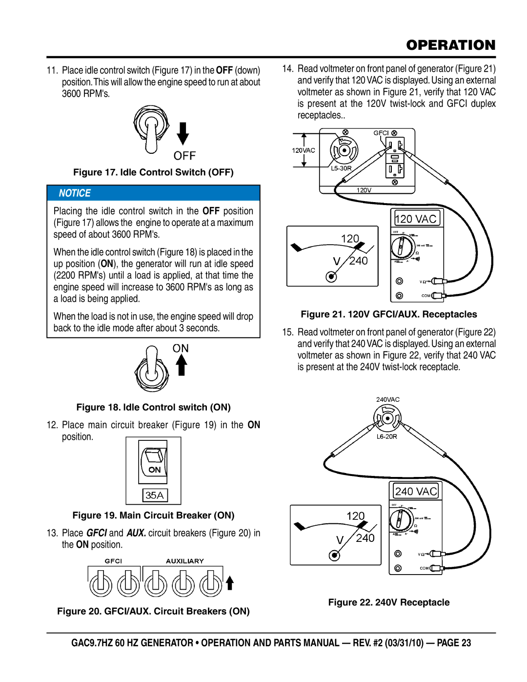
11.Place idle control switch (Figure 17) in the OFF (down) position.This will allow the engine speed to run at about 3600 RPM's.
14.Read voltmeter on front panel of generator (Figure 21) and verify that 120 VAC is displayed. Using an external voltmeter as shown in Figure 21, verify that 120 VAC is present at the 120V
Figure 17. Idle Control Switch (OFF)
![]() NOTICE
NOTICE
Placing the idle control switch in the OFF position (Figure 17) allows the engine to operate at a maximum speed of about 3600 RPM's.
When the idle control switch (Figure 18) is placed in the up position (ON), the generator will run at idle speed (2200 RPM's) until a load is applied, at that time the engine speed will increase to 3600 RPM's as long as a load is being applied.
When the load is not in use, the engine speed will drop back to the idle mode after about 3 seconds.
Figure 18. Idle Control switch (ON)
12.Place main circuit breaker (Figure 19) in the ON position.
Figure 19. Main Circuit Breaker (ON)
13.Place GFCI and AUX. circuit breakers (Figure 20) in the ON position.
Figure 20. GFCI/AUX. Circuit Breakers (ON)
Figure 21. 120V GFCI/AUX. Receptacles
15.Read voltmeter on front panel of generator (Figure 22) and verify that 240 VAC is displayed. Using an external voltmeter as shown in Figure 22, verify that 240 VAC is present at the 240V
Figure 22. 240V Receptacle
GAC9.7HZ 60 hz GENERATOR • operation and parts manual — rev. #2 (03/31/10) — page 23
