NAD C 372 owner manual Bare Wires And Pin Connectors, Switched Ac Outlet, Iec Ac Mains Power Input

Models: C 372

1 68
Download 68 pages 62.21 Kb
Page 6
Image 6
BARE WIRES AND PIN CONNECTORS

ENGLISH FRANÇAIS DEUTSCH ESPAÑOL ITALIANO PORTUGUÊS SVENSKA

Under normal operation, connect the right speaker to the terminals market 'R +' and 'R-' ensuring that the 'R+' is connected to the '+' terminal on your loudspeaker and the 'R-' is connected to the loudspeaker's '-' terminal. Connect the terminals marked 'L+' and 'L-' to the left speaker in the same way.

In Bridge Mode, connect the single speaker to the terminals marked 'R +' and 'L+' ensuring that the 'L+' is connected to the '+' terminal on your loudspeaker and the 'L+' is connected to the loudspeaker's '-' terminal. Refer also to section "Bridging" in this chapter (No. 12).

Always use heavy duty (16 gauge; 1.5mm, or thicker) stranded wire to connect loudspeakers to your NAD C 372. The high-current binding post terminals can be used as a screw terminal for cables terminating in spade or pin sockets or for cables with bare wire ends.

BARE WIRES AND PIN CONNECTORS

Bare wires and pin sockets should be inserted into the hole in the shaft of the terminal. Unscrew the speaker terminal's plastic bushing until the hole in the screw shaft is revealed. Insert the pin or bare cable end into the hole and secure the cable by tightening down the terminal's bushing. Ensure bare wire from the speaker cables does not touch the back panel or another socket . Ensure that there is only 1/2" (1cm) of bare cable or pin and no loose strands of speakers wire.

NOTE: Make sure the speaker impedance is 4 ohms or more when connecting only one pair of speakers; make sure the speaker impedance for all speakers is more then 8 ohms when connecting two sets of speakers. In Bridge Mode, the impedance of the loudspeaker should also be 8 ohms or higher.

17. SWITCHED AC OUTLET

The AC power cord of another component may be plugged into this accessory outlet. Components plugged into this outlet will be switched On and Off by the POWER button on the front panel or by the ON and STAND-BY button on the remote control handset.

NOTE: The total power consumption of any components connected to the AC outlets may not exceed 100 Watts.

18. IEC AC MAINS (POWER) INPUT

The C 372 comes supplied with a separate AC Mains cable. Before connecting the cable to a live wall socket ensure that it is firmly connected to the NAD C 372's AC Mains input socket first. Always disconnect the AC Mains cable plug from the live wall socket first, before disconnecting the cable from the C 372 Mains input socket.

FRONT PANEL CONTROLS (FIGURE 2)

1. POWER ON/OFF

Press the POWER button to switch the amplifier On. The Stand-by indicator (No. 2) over the power button will light up amber and after a short pause will turn to green to indicate the amplifier is now ready for normal operation.

Pressing the POWER switch again will turn the unit OFF completely, it will not respond to the remote control.

REMOTE CONTROL (FIGURE 3) ON AND OFF BUTTONS

Press the POWER button to switch the amplifier On. The Stand-by indicator (No. 2) over the power button will light up amber. Pressing the POWER switch again will turn the unit OFF completely, it will not respond to the remote control. The NAD C 372 remote has a separate On and Off button. This can be particularly useful to keep components within a system "in sync": This way all components will switch to stand- by when Off is pressed or switch to operating mode when On is pressed, instead of some components switching On when the amplifier is switched to Stand-by. (Note that the other components have to be capable of responding to the separate On and Off commands as well). Press the ON button to switch the unit from Stand-by to the operating mode; The Stand-by indicator (Fig. 2; No. 2) will turn from amber to red, then to green and the indicator for the last selected input will blink and light up. Press the OFF button to switch the unit to the Stand-by mode: The Stand-by indicator will light up amber.

NOTE: In Stand-by mode the C 372 uses very little power. However, it is recommended that you switch the unit totally off if it is not going to be used for more than a couple of days. Switch off completely by pressing the POWER button on the front panel (No. 1), all lights will extinguish.

2. POWER / STAND-BY / PROTECTION INDICATOR

Upon switching the power on, the LED will light up amber in standby state. While one of the input select buttons is pressed, the LED will turn red for a moment, then turn green for ON state. In cases of serious abuse of the amplifier, such as overheating, excessively low loudspeaker impedance, short circuit etc. the amplifier will engage its Protection circuitry, indicated by the LED turning from green to red, and the sound being muted. In such a case, turn the amplifier off, wait for it to cool down and/or check the speaker connections, making sure the overall loudspeaker impedance doesn’t go below 4 ohms. Once the cause for the protection circuitry to engage has been removed, press Power again to resume normal operation.

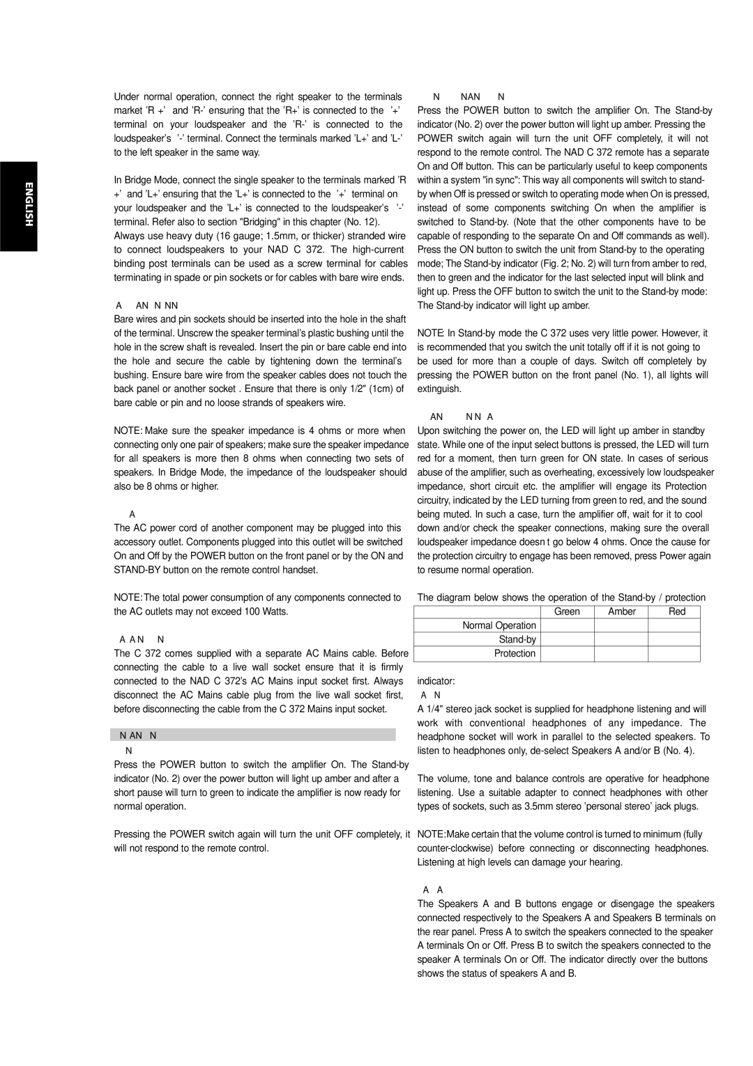
The diagram below shows the operation of the Stand-by / protection


Green

Amber

Red

Normal Operation


Stand-by


Protection


indicator:

3. HEADPHONE SOCKET

A 1/4" stereo jack socket is supplied for headphone listening and will work with conventional headphones of any impedance. The headphone socket will work in parallel to the selected speakers. To listen to headphones only, de-select Speakers A and/or B (No. 4).

The volume, tone and balance controls are operative for headphone listening. Use a suitable adapter to connect headphones with other types of sockets, such as 3.5mm stereo 'personal stereo' jack plugs.

NOTE: Make certain that the volume control is turned to minimum (fully counter-clockwise) before connecting or disconnecting headphones. Listening at high levels can damage your hearing.

4. SPEAKERS A & B

The Speakers A and B buttons engage or disengage the speakers connected respectively to the Speakers A and Speakers B terminals on the rear panel. Press A to switch the speakers connected to the speaker A terminals On or Off. Press B to switch the speakers connected to the speaker A terminals On or Off. The indicator directly over the buttons shows the status of speakers A and B.

6

Page 6
Image 6
NAD C 372 Bare Wires And Pin Connectors, Switched Ac Outlet, Iec Ac Mains Power Input, Front Panel Controls . Power On/Off