12
GENERAL VENTING
PELLET VENT MUST MAINTAIN A MINIMUM 3" CLEARANCE TO ANY COMBUSTIBLE (install vent at clearances specifi ed by the vent manufacturer).
DO NOT CONNECT THE PELLET VENT TO A VENT OR CHIM- NEY SERVING ANY OTHER APPLIANCE OR HEATER.
DO NOT INSTALL A FLUE DAMPER IN THE EXHAUST VENT- ING SYSTEM OF THIS UNIT.
TYPE OF VENT
Must be an approved 3" or 4" Diameter Type "L" or "PL" vent, vented to the outside or connect the vent to a factory built type "A" chimney using an adaptor; and/or stainless steel chimney liner for masonry fi replace installations. Use 4" diameter vent if vent or liner height is over 15' or if installation is over 4,000' above sea level.
INSTALLING THE PELLET VENT
The vent must have a support bracket every 5' when on the exte- rior wall.
To achieve optimum performance, keep vent runs as short as pos- sible, especially on horizontal installations.
MAXIMUM VENTING:
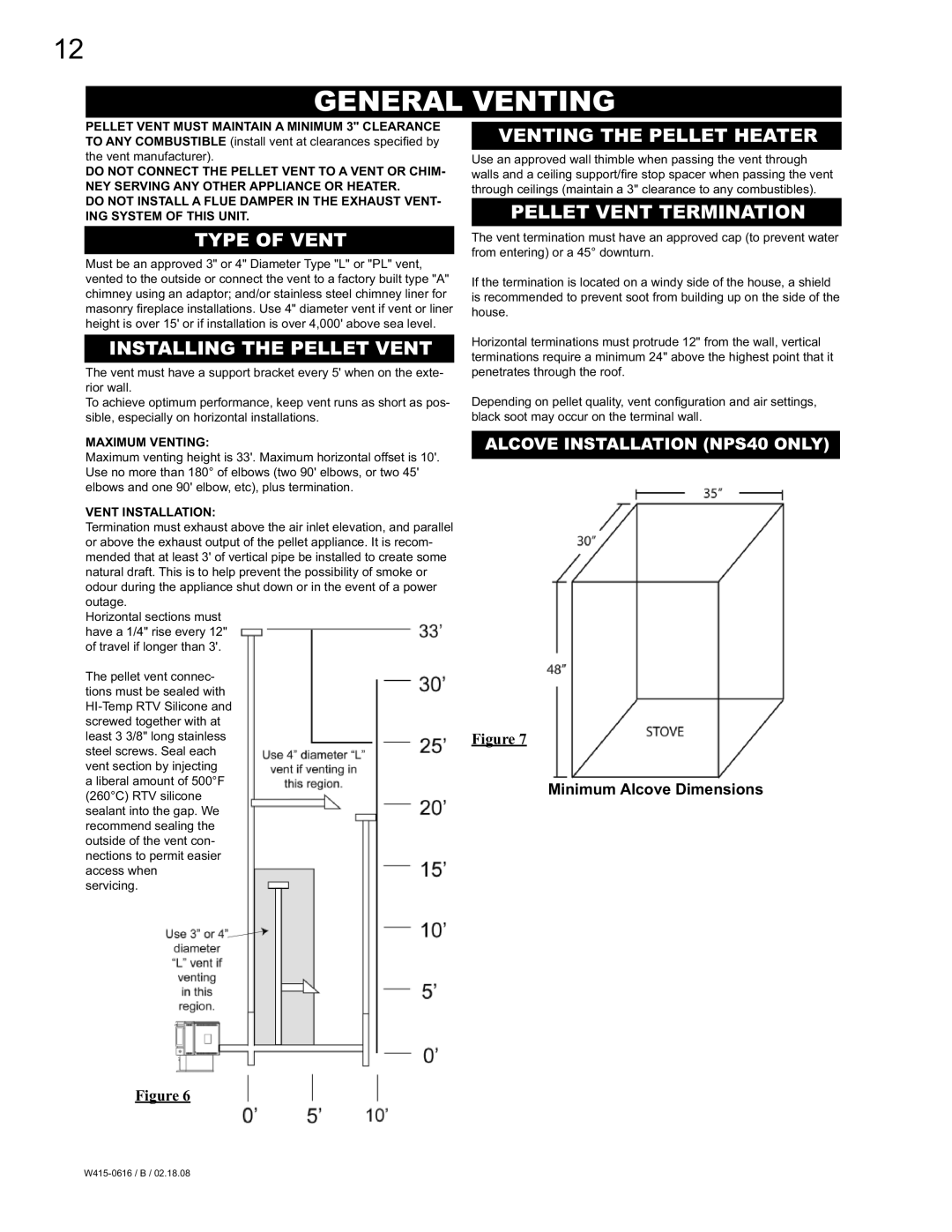
Maximum venting height is 33'. Maximum horizontal offset is 10'. Use no more than 180° of elbows (two 90' elbows, or two 45' elbows and one 90' elbow, etc), plus termination.
VENT INSTALLATION:
Termination must exhaust above the air inlet elevation, and parallel or above the exhaust output of the pellet appliance. It is recom- mended that at least 3' of vertical pipe be installed to create some natural draft. This is to help prevent the possibility of smoke or odour during the appliance shut down or in the event of a power outage.
Horizontal sections must have a 1/4" rise every 12" of travel if longer than 3'.
The pellet vent connec- tions must be sealed with
VENTING THE PELLET HEATER
Use an approved wall thimble when passing the vent through walls and a ceiling support/fi re stop spacer when passing the vent through ceilings (maintain a 3" clearance to any combustibles).
PELLET VENT TERMINATION
The vent termination must have an approved cap (to prevent water from entering) or a 45° downturn.
If the termination is located on a windy side of the house, a shield is recommended to prevent soot from building up on the side of the house.
Horizontal terminations must protrude 12" from the wall, vertical terminations require a minimum 24" above the highest point that it penetrates through the roof.
Depending on pellet quality, vent confi guration and air settings, black soot may occur on the terminal wall.
ALCOVE INSTALLATION (NPS40 ONLY)
Figure 7
Minimum Alcove Dimensions
Figure 6
