Terminal Panel
5 6
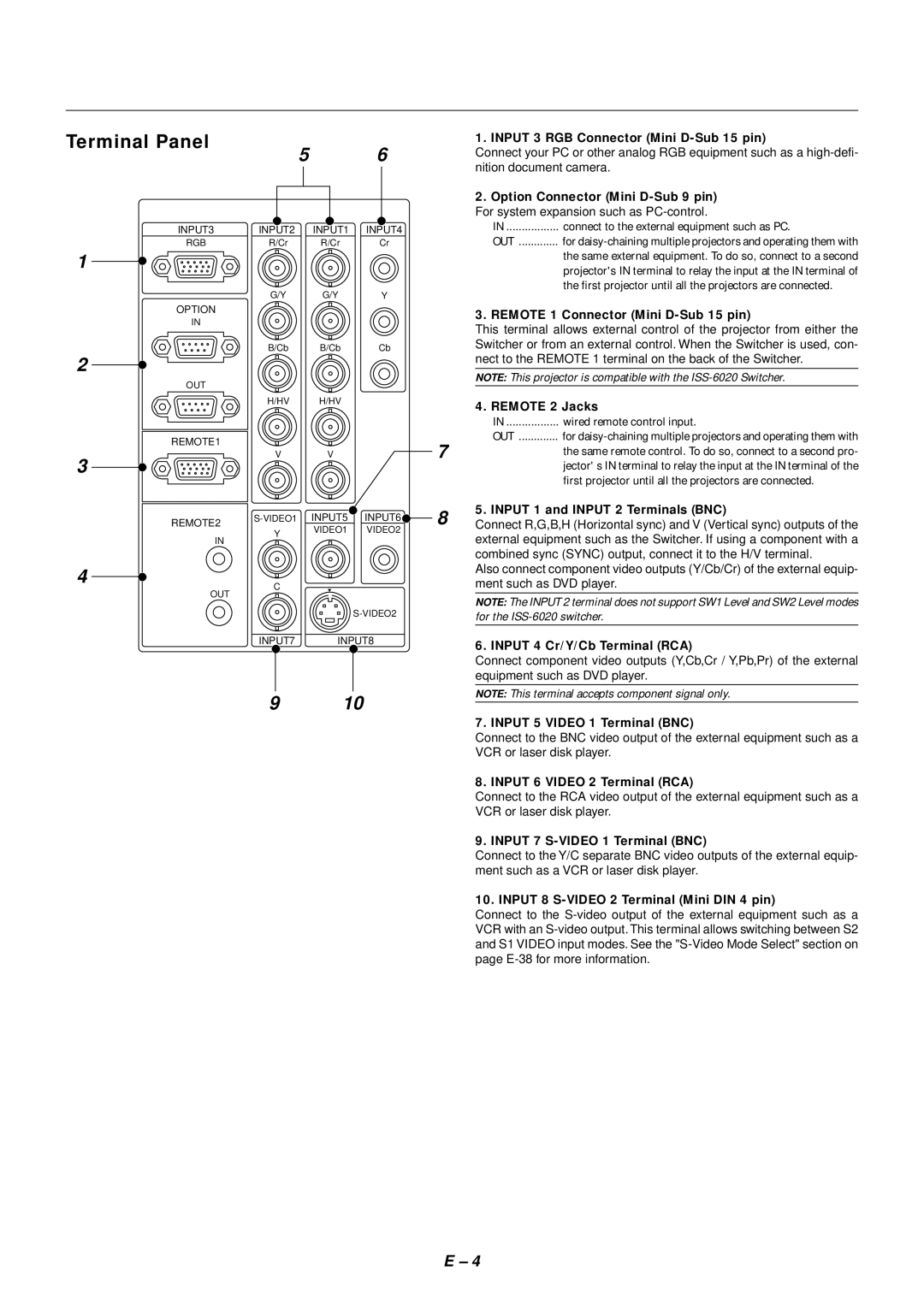
INPUT3 | INPUT2 | INPUT1 | INPUT4 |
RGB | R/Cr | R/Cr | Cr |
1 |
|
|
|
| G/Y | G/Y | Y |
1. INPUT 3 RGB Connector (Mini
Connect your PC or other analog RGB equipment such as a
2.Option Connector (Mini D-Sub 9 pin)
For system expansion such as
IN | connect to the external equipment such as PC. |
OUT | for |
| the same external equipment. To do so, connect to a second |
| projector's IN terminal to relay the input at the IN terminal of |
| the first projector until all the projectors are connected. |
OPTION
IN
2
OUT
REMOTE1
3
REMOTE2
IN
4
OUT
3. REMOTE 1 Connector (Mini D-Sub 15 pin)
This terminal allows external control of the projector from either the
B/Cb B/Cb CbSwitcher or from an external control. When the Switcher is used, con- nect to the REMOTE 1 terminal on the back of the Switcher.
NOTE: This projector is compatible with the
H/HV | H/HV | 4. REMOTE 2 Jacks | |
|
| ||
|
| IN | wired remote control input. |
|
| OUT | for |
V | V | 7 | the same remote control. To do so, connect to a second pro- |
|
|
| jector' s IN terminal to relay the input at the IN terminal of the |
first projector until all the projectors are connected.
INPUT5 | INPUT6 | 8 | 5. INPUT 1 and INPUT 2 Terminals (BNC) | ||
Connect R,G,B,H (Horizontal sync) and V (Vertical sync) outputs of the | |||||
Y | VIDEO1 | VIDEO2 | |||
| external equipment such as the Switcher. If using a component with a | ||||
|
|
| |||
|
|
|
| ||
|
|
|
| combined sync (SYNC) output, connect it to the H/V terminal. | |
|
|
|
| Also connect component video outputs (Y/Cb/Cr) of the external equip- | |
C |
|
|
| ment such as DVD player. | |
|
|
| NOTE: The INPUT 2 terminal does not support SW1 Level and SW2 Level modes | ||
|
|
| for the | ||
INPUT7 | INPUT8 |
| 6. INPUT 4 Cr/Y/Cb Terminal (RCA) | ||
|
|
|
| ||
|
|
|
| Connect component video outputs (Y,Cb,Cr / Y,Pb,Pr) of the external | |
|
|
|
| equipment such as DVD player. | |
9 | 10 |
| NOTE: This terminal accepts component signal only. | ||
|
| ||||
|
|
|
| 7. INPUT 5 VIDEO 1 Terminal (BNC) | |
|
|
|
| Connect to the BNC video output of the external equipment such as a | |
|
|
|
| VCR or laser disk player. | |
|
|
|
| 8. INPUT 6 VIDEO 2 Terminal (RCA) | |
|
|
|
| Connect to the RCA video output of the external equipment such as a | |
|
|
|
| VCR or laser disk player. | |
|
|
|
| 9. INPUT 7 | |
|
|
|
| Connect to the Y/C separate BNC video outputs of the external equip- | |
|
|
|
| ment such as a VCR or laser disk player. | |
|
|
|
| 10. INPUT 8 | |
|
|
|
| Connect to the | |
|
|
|
| VCR with an | |
|
|
|
| and S1 VIDEO input modes. See the | |
|
|
|
| page | |
E – 4