When Used with One Switcher (ISS-6020/ISS-6020G)
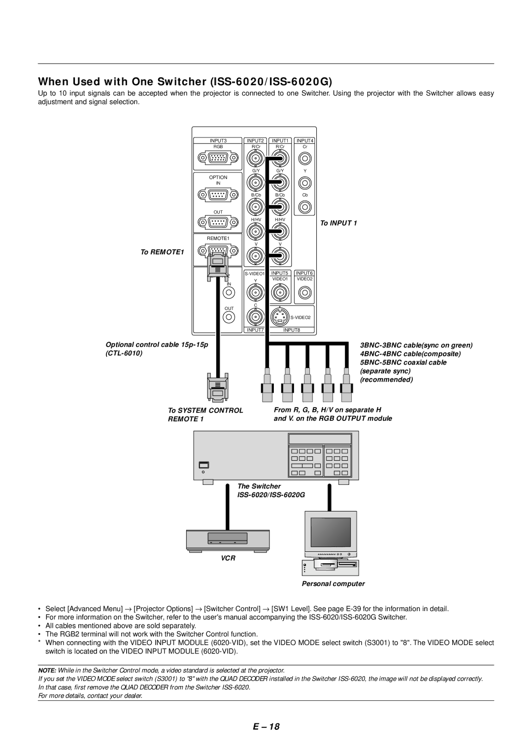
Up to 10 input signals can be accepted when the projector is connected to one Switcher. Using the projector with the Switcher allows easy adjustment and signal selection.
INPUT3 | INPUT2 | INPUT1 | INPUT4 |
RGB | R/Cr | R/Cr | Cr |
| G/Y | G/Y | Y |
OPTION |
|
|
|
IN |
|
|
|
| B/Cb | B/Cb | Cb |
OUT |
|
|
|
| H/HV | H/HV | To INPUT 1 |
|
|
| |
REMOTE1 |
|
|
|
| V | V |
|
To REMOTE1 |
|
|
|
| INPUT6 | ||
| Y | VIDEO1 | VIDEO2 |
IN |
|
| |
|
|
| |
OUT | C |
|
|
|
|
| |
|
|
| |
| INPUT7 | INPUT8 | |
Optional control cable |
|
|
|
|
|
| |
(recommended)
To SYSTEM CONTROL | From R, G, B, H/V on separate H | |||||
REMOTE 1 | and V. on the RGB OUTPUT module | |||||
|
|
|
|
|
|
|
|
|
|
|
|
|
|
|
|
|
|
|
|
|
|
|
|
|
|
|
|
The Switcher
VCR
Personal computer
• Select [Advanced Menu] → [Projector Options] → [Switcher Control] → [SW1 Level]. See page
•For more information on the Switcher, refer to the user's manual accompanying the
•All cables mentioned above are sold separately.
•The RGB2 terminal will not work with the Switcher Control function.
*When connecting with the VIDEO INPUT MODULE
NOTE: While in the Switcher Control mode, a video standard is selected at the projector.
If you set the VIDEO MODE select switch (S3001) to "8" with the QUAD DECODER installed in the Switcher
For more details, contact your dealer.
E – 18