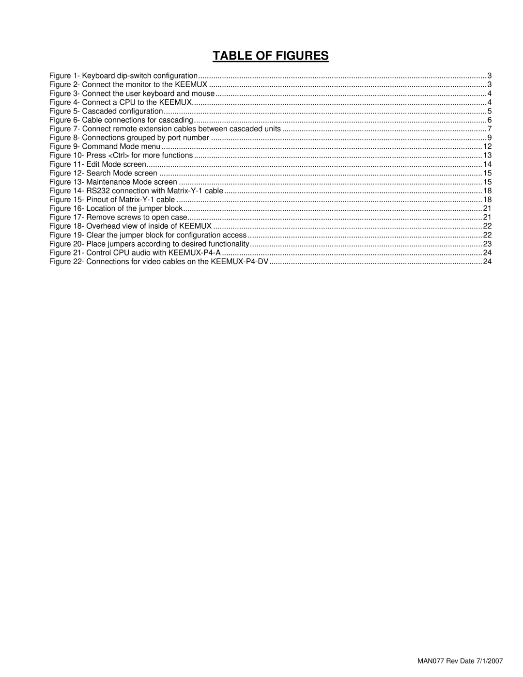
TABLE OF FIGURES |
|
Figure 1- Keyboard | 3 |
Figure 2- Connect the monitor to the KEEMUX | 3 |
Figure 3- Connect the user keyboard and mouse | 4 |
Figure 4- Connect a CPU to the KEEMUX | 4 |
Figure 5- Cascaded configuration | 5 |
Figure 6- Cable connections for cascading | 6 |
Figure 7- Connect remote extension cables between cascaded units | 7 |
Figure 8- Connections grouped by port number | 9 |
Figure 9- Command Mode menu | 12 |
Figure 10- Press <Ctrl> for more functions | 13 |
Figure 11- Edit Mode screen | 14 |
Figure 12- Search Mode screen | 15 |
Figure 13- Maintenance Mode screen | 15 |
Figure 14- RS232 connection with | 18 |
Figure 15- Pinout of | 18 |
Figure 16- Location of the jumper block | 21 |
Figure 17- Remove screws to open case | 21 |
Figure 18- Overhead view of inside of KEEMUX | 22 |
Figure 19- Clear the jumper block for configuration access | 22 |
Figure 20- Place jumpers according to desired functionality | 23 |
Figure 21- Control CPU audio with | 24 |
Figure 22- Connections for video cables on the | 24 |
Page 4
Image 4
