NTI KEEMUX Series PS/2 KVM Switch
NOTE: Before proceeding, it is important to discharge any static charge you may be carrying by touching any large metal object (away from the KEEMUX).
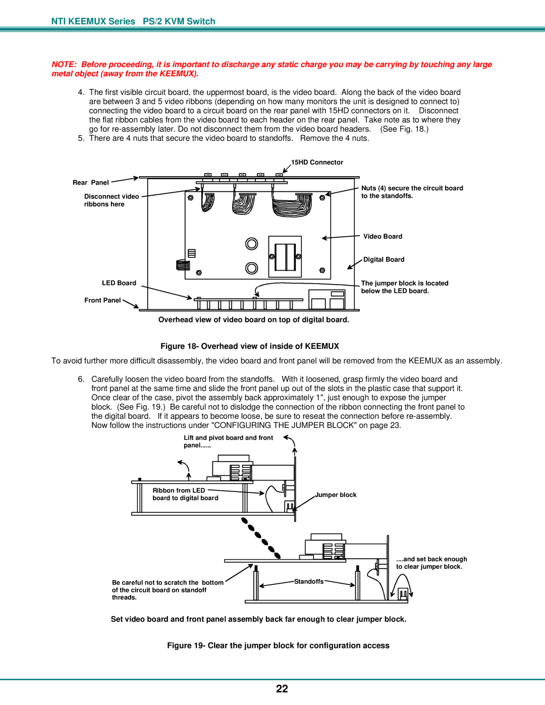
4.The first visible circuit board, the uppermost board, is the video board. Along the back of the video board are between 3 and 5 video ribbons (depending on how many monitors the unit is designed to connect to) connecting the video board to a circuit board on the rear panel with 15HD connectors on it. Disconnect the flat ribbon cables from the video board to each header on the rear panel. Take note as to where they go for
5.There are 4 nuts that secure the video board to standoffs. Remove the 4 nuts.
Rear Panel ![]()
Disconnect video ![]() ribbons here
ribbons here
LED Board
Front Panel
15HD Connector
Nuts (4) secure the circuit board to the standoffs.
![]() Video Board
Video Board
Digital Board
The jumper block is located below the LED board.
Overhead view of video board on top of digital board.
Figure 18- Overhead view of inside of KEEMUX
To avoid further more difficult disassembly, the video board and front panel will be removed from the KEEMUX as an assembly.
6.Carefully loosen the video board from the standoffs. With it loosened, grasp firmly the video board and front panel at the same time and slide the front panel up out of the slots in the plastic case that support it. Once clear of the case, pivot the assembly back approximately 1", just enough to expose the jumper block. (See Fig. 19.) Be careful not to dislodge the connection of the ribbon connecting the front panel to the digital board. If it appears to become loose, be sure to reseat the connection before
Lift and pivot board and front
panel......
Ribbon from LED ![]() board to digital board
board to digital board
Jumper block
Be careful not to scratch the bottom ![]()
![]() Standoffs
Standoffs ![]() of the circuit board on standoff
of the circuit board on standoff
threads.
....and set back enough
to clear jumper block.
Set video board and front panel assembly back far enough to clear jumper block.
Figure 19- Clear the jumper block for configuration access
22