NTI KEEMUX Series PS/2 KVM Switch
Configuring The Jumper Block
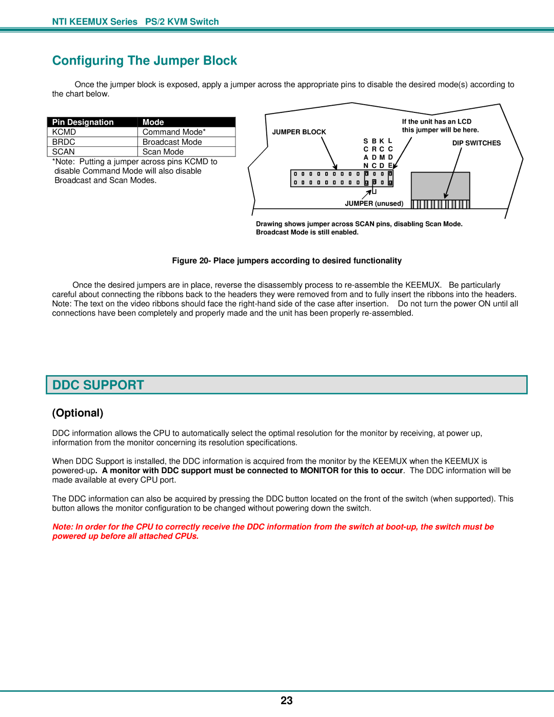
Once the jumper block is exposed, apply a jumper across the appropriate pins to disable the desired mode(s) according to the chart below.
Pin Designation | Mode | |
KCMD | Command Mode* | |
BRDC | Broadcast Mode | |
SCAN | Scan Mode |
*Note: Putting a jumper across pins KCMD to disable Command Mode will also disable Broadcast and Scan Modes.
|
|
|
|
|
|
|
|
|
|
|
|
|
|
|
|
|
|
|
|
|
|
|
|
|
|
| If the unit has an LCD |
JUMPER BLOCK | this jumper will be here. | ||||||||||||||||||||||||||
|
|
|
|
|
|
|
|
|
|
|
|
|
|
|
|
|
|
| S B K L | DIP SWITCHES | |||||||
|
|
|
|
|
|
|
|
|
|
|
|
|
|
|
|
|
|
| C R C C |
| |||||||
|
|
|
|
|
|
|
|
|
|
|
|
|
|
|
|
|
|
| A D M D |
| |||||||
|
|
|
|
|
|
|
|
|
|
|
|
|
|
|
|
|
|
| N C D E |
| |||||||
|
|
|
|
|
|
|
|
|
|
|
|
|
|
|
|
|
|
|
|
|
|
|
|
|
|
|
|
|
|
|
|
|
|
|
|
|
|
|
|
|
|
|
|
|
|
|
|
|
|
|
|
|
|
|
|
|
|
|
|
|
|
|
|
|
|
|
|
|
|
|
|
|
|
|
|
|
|
|
|
|
|
|
|
|
|
|
|
|
|
|
|
|
|
|
|
|
|
|
|
|
|
|
|
|
|
|
|
|
|
|
|
JUMPER (unused)
Drawing shows jumper across SCAN pins, disabling Scan Mode. Broadcast Mode is still enabled.
Figure 20- Place jumpers according to desired functionality
Once the desired jumpers are in place, reverse the disassembly process to
DDC SUPPORT
(Optional)
DDC information allows the CPU to automatically select the optimal resolution for the monitor by receiving, at power up, information from the monitor concerning its resolution specifications.
When DDC Support is installed, the DDC information is acquired from the monitor by the KEEMUX when the KEEMUX is
The DDC information can also be acquired by pressing the DDC button located on the front of the switch (when supported). This button allows the monitor configuration to be changed without powering down the switch.
Note: In order for the CPU to correctly receive the DDC information from the switch at
23